30+ Wiring Diagram Panel Ats Amf Pdf PNG Wiring Consultants
Understanding Wiring Diagrams to Connect an ATS to a GeneratorThe wiring diagram is a crucial component of any home or business electrical system. This document illustrates how the generator, automatic transfer switch (ATS), circuit breakers, and other components are connected together. Before attempting any connections within the electrical system, it is important to understand the basics of.
Wiring Diagram Ats Genset Wiring Digital and Schematic
A wiring diagram ATS/AMF is a visual representation of the electrical connections and components in a system. The diagram typically shows the various components of the system, as well as their sizes and shapes, and shows how they are connected. It also usually includes labels to identify each component. Understanding how to read and interpret a.
Wiring Diagram Panel Ats Amf Wiring Flow Schema
#Emko Trans-AMF Automatic Genset Controller with Transfer Switch wiring pdf diagram explain #wiring #Emkopdf #Wiring #generatorwiringTrans-AMF - Automatic Ge.
Wiring Diagrams For Ats To Generator Wiring Diagram
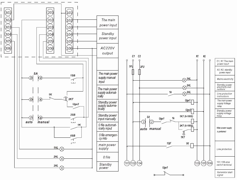
TYPICAL ATS PANEL WIRING DIAGRAM. GENERATOR-LOAD The generator is electrically connected to the LOAD via the KG (contactor of the generator). This is possible only when KM is open. The KM-AUX are the auxiliary contacts fitted on the body of the KM.. The BE242 is the only AMF ATS controller of square size that requires a round hole. This.

PLN Single Phase ATS Circuit Connection Diagram to Genset Using Two Contactors YouTube
Wiring Diagram Panel ATS AMF PDF is an essential tool when it comes to understanding how electrical systems are wired and operated. Wiring diagram panel ATS/AMF PDF diagrams can be used to diagnose problems with existing wiring systems or to design new installations. They allow technicians to trace the flow of wires, check for continuity.
️Wiring Diagram Ats Amf Genset Free Download Gambr.co
#sumberteknik #seputargenset #panelamfatshttps://drive.google.com/file/d/1fQJ9Is5LVRwRRSJoJz6SEqs79jSw1p1t/view?usp=sharing
[44+] Wiring Diagram Ats Amf Genset
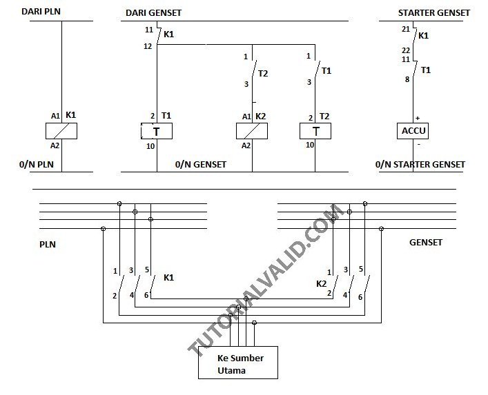
Gambar di atas merupakan rangakain atau wiring diagram kontrol sistem ATS AMF. Adapun komponen yang ada pada rangkaian di atas adalah K1 kontaktor PLN, K2 Genset, T1 timer off delay, T2 timer on delay, fuel bahan bakar genset dan Accu aki untuk starting genset. Ada tiga bagian utama pada rangkaian kontrol ATS/AMF di atas yaitu sebagai berikut. a.
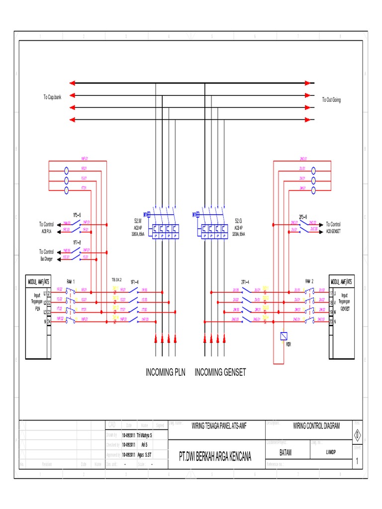
Wiring Tenaga Panel AtsAmf
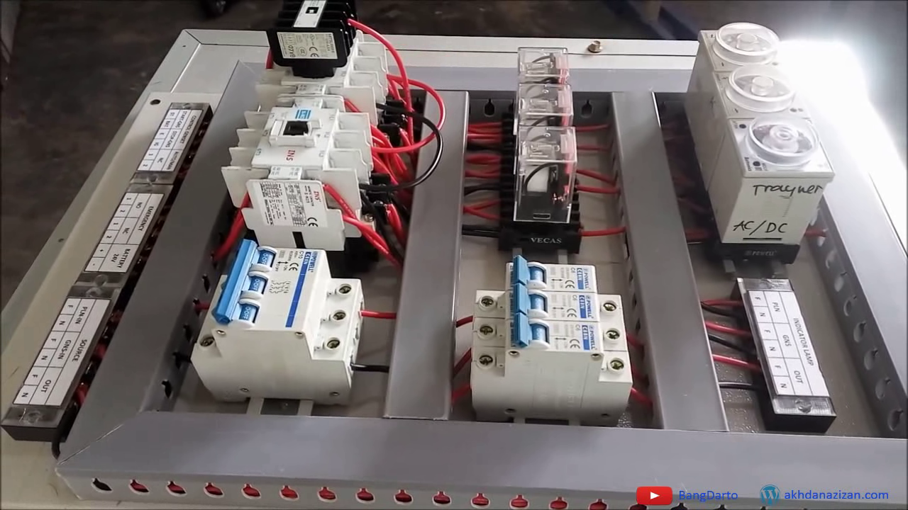
This video is an overview of the connections required to build a WORLD CLASS Automatic Mains Failure Control Panel. Read more at https://bernini-design.com

Membuat Panel AMF ATS (switch genset otomatis)
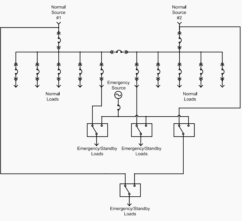
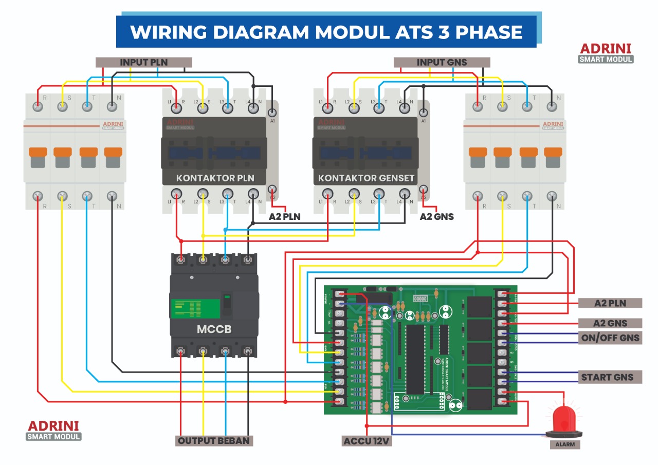
Wiring diagrams for ATS Gensets typically consist of four main sections: the power input, the transfer switch and the generator circuit. The power input section is where power from the utility company or other source is connected. The transfer switch section contains all the wiring associated with connecting the two power sources together.

[DIAGRAM] Wiring Diagram Panel Ats Genset
Automatic mains failure (AMF) panels, often referred to as automatic transfer switch (ATS) panels, make the power switch to emergency standby generators in the event of a significant loss of mains power or total blackout. Without AMF panels, generators need to be operated manually and that can mean lost data, potential damage to electrical.

Wiring panel ATS dan AMF PLN Genset start otomatis VOLTECHNO
Products DSEGenset ® DSEControl ® DSEPower ® DSEAts ® About Us Videos News Case Studies Careers Support Product Software Product Downloads Support FAQs Genset Non-Standard/Obsolete Control Non-Standard/Obsolete ATS Non-Standard/Obsolete Power Non-Standard/Obsolete Purchasing Terms & Conditions

Wiring Diagram Ats Genset Wiring Digital and Schematic
3 - Working Principle of AMF panel: When the AMF panel senses that mains has failed then it provides a start signal to the DG. After starting the DG, the breaker is connected to the load. This all activity has been done in automatically. When backup supply is detected then AMF panel sends a tripping signal to the DG breaker after tripping DG.
Wiring Diagram Kunci Kontak Genset Wiring Diagram and Schematics
Sistem AMF (Automatic Main Failure) adalah suatu sistem kendali yang berguna untuk menyalakan mesin genset (starter mesin genset) ketika beban yang disuplai suatu tegangan kehilangan sumber tegangan listriknya utamanya seperti contoh yang kita bahas yaitu PLN. Jadi cara kerja dari sistem yang akan kita buat adalah ketika beban kehilangan sumber.

Wiring Diagram Ats Amf Genset Home Wiring Diagram
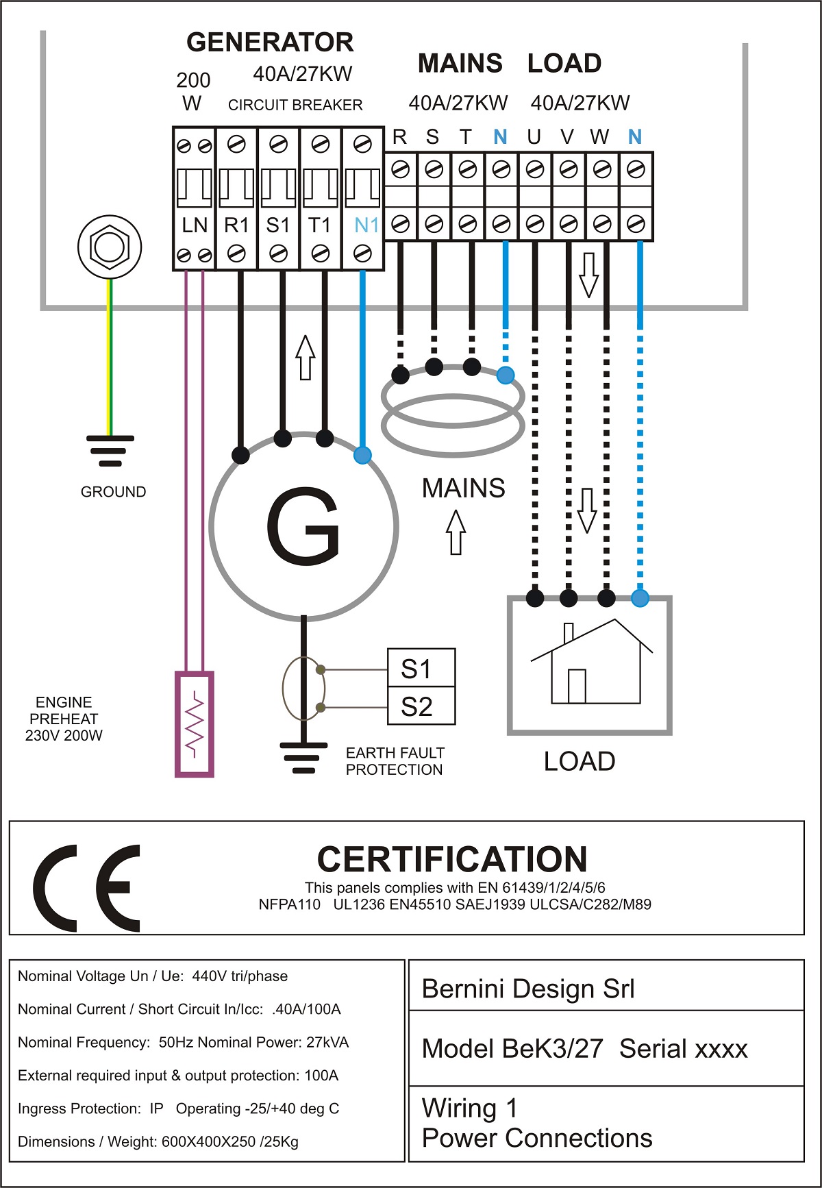
This AMF panel wiring diagram illustrates the connections of the BeK3 AMF controller. It monitors the parameters of the mains and automatically starts the engine via relays. Once the generator provides the correct frequency and voltage, the controller transfers the load from the mains to the generator. This happens after a mains failure.
[DIAGRAM] Wiring Diagram Panel Ats Genset
The main difference between the two types of generator panels is the way they're started. ATS panels use a volt-free contact system with the mounted set control panel to start and stop the generator. However, AMF panels have a dedicated generator controller with alarms for stop, start, water temperature, fuel oil pressure and full level.

[DIAGRAM] Wiring Diagram Ats Amf Genset
The Crucial Role of Wiring Diagrams in ATS and AMF Systems: 1. Seamless Power Transitions: ATS systems are designed to automatically switch between the primary power source (often the grid) and a secondary power source (typically a generator) during power outages. Wiring diagrams are instrumental in understanding how this transition occurs.