4 INFO ISO STANDARD H7 2020 * ISOStandard
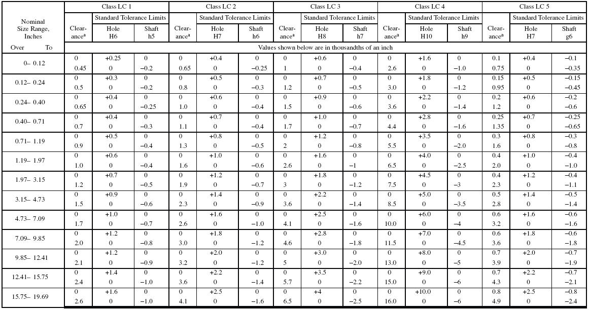
98.43 - 124.02. 0. 210. -173. -38. 38. 383. Complete charts for H7/g6 Clearance Fit per ISO 286, including size limits for hole and shaft and clearance classification data.
Toleransi H7
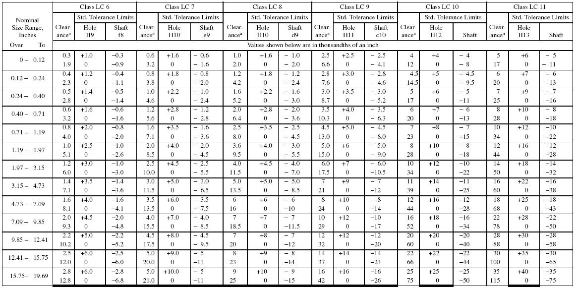
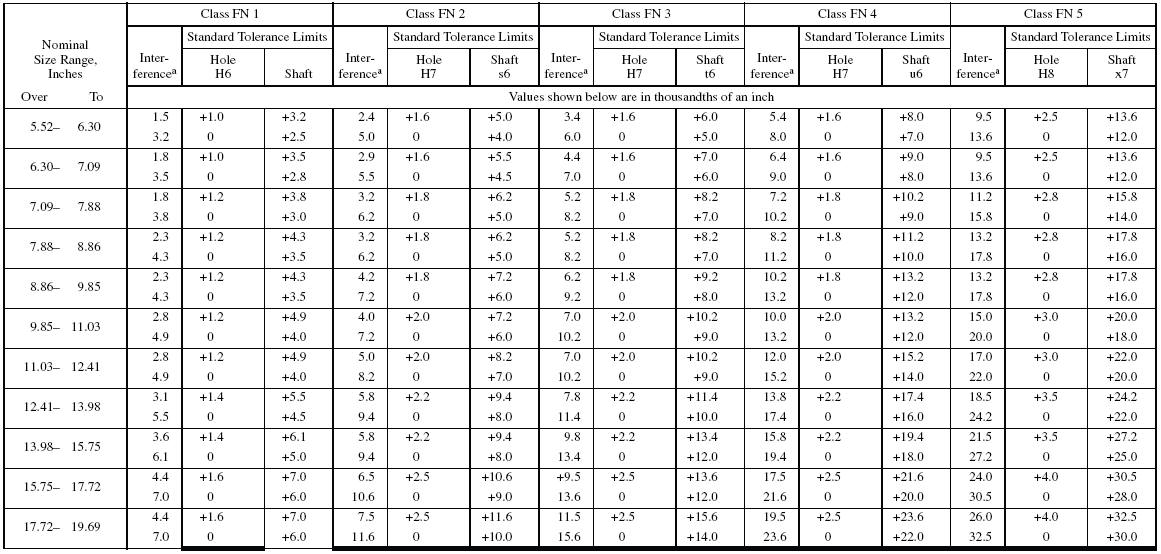
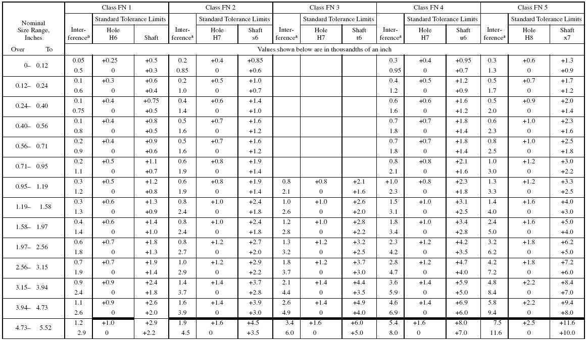
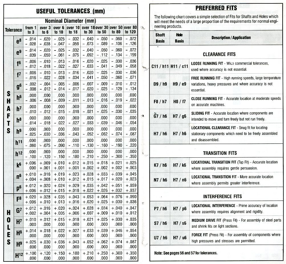
H7/s6: S7/h6: Medium drive fit for ordinary steel parts or shrink fits on light sections, the tightest fit usable with cast iron. H7/u6: U7/h6: Force fit suitable for parts which can be highly stressed or for shrink fits where the heavy pressing forces required are impractical. Preferred fits table (ANSI B4.2-1978) Basic.

Cotation Tolérancée et ajustemen
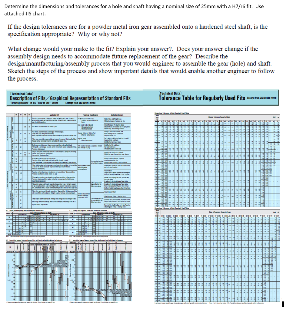
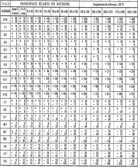
H7 H6 G7 G6 F8 F7 F6 E9 E8 E7 D10 D9 D8 C10 C9 B10 ( mm ) Note: In each column, the upper figure is the upper dimensional tolerance, and the lower figure is the lower dimensional tolera Hole tolerance range class nce. Hole dimensional tolerances for regularly used ˜tting Units: µ m Standard dimension More than Not more than
H7 Hole Tolerance A Pictures Of Hole 2018
Fits and tolerance calculator for shaft and hole tolerance calculation according to ISO 286-1 and ANSI B4.2 metric standards . The schematic representation of the fit is also drawn by tolerance calculator. The tolerances defined in ISO 286-1 are applicable to size range from 0 mm to 3150 mm but there are exceptional cases defined in the.
H7 Hole Tolerance A Pictures Of Hole 2018
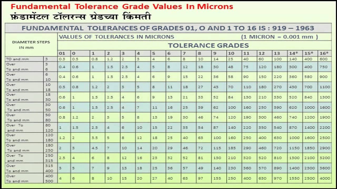
1) Values for standard tolerance grades IT01 and IT0 for basic sizes less than or equal to 500 mm are given in IS0 286-1, annex A, table 5. 2) Values for standard tolerance grades IT1 to IT5 (incl.) for basic sizes over 500 mm are included for experimental use.
H7 Hole Tolerance A Pictures Of Hole 2018
Engineering fit. Engineering fits are generally used as part of geometric dimensioning and tolerancing when a part or assembly is designed. In engineering terms, the "fit" is the clearance between two mating parts, and the size of this clearance determines whether the parts can, at one end of the spectrum, move or rotate independently from each.
Iso 2768 hole tolerance h7 lasopaback
H7 +10 0 +12 0 +15 0 +18 0 +21 0 +25 0 +30 0 +35 0 +40 0: H11 +60 0 +75 0 +90 0 +110 0 +130 0 +160 0 +190 0 +220 0 +250 0: H12 +100 0 +120 0 +150 0 +180 0 +210 0 +250 0 +300 0 +350 0 +400 0: This information is provided as a reference only and may vary depending on the manufacturer. Home Company Products News & Info; Home: Company Info: Browse.
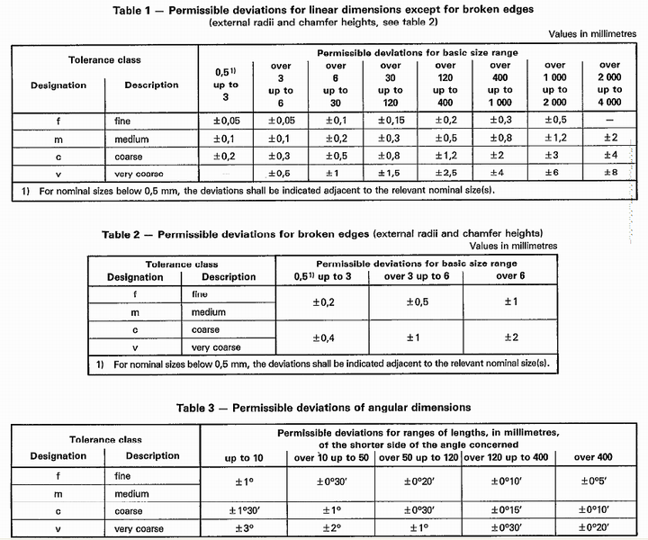
Iso 2768 Hole Tolerance H7
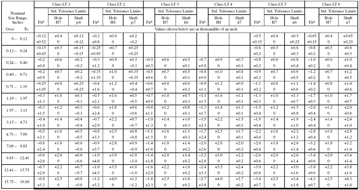
Example fits: H7/k6 for hole-basis and K7/h6 for shaft-basis. Using a 25 mm diameter, a H7/k6 fit gives a max clearance of 0.019 mm and a max interference of 0.015 mm. Fixed Fit. Leaves a small clearance or creates a small interference. Assembly is possible using light force. Example uses in engineering: Driven bushes, armatures on shafts, etc.
H7 Hole Tolerance A Pictures Of Hole 2018
H6 H7 H8 H9 Applicable Part Functional Classification Application Example Can be Moved Relatively Clearance Fit Loose Fit c9 Part which accommodates a wide gap or moving part which needs a gap. Part which accommodates a wide gap to facilitate assembling. Part which needs an appropriate gap even at a high temperature. Part whose structure needs.
Iso 2768 hole tolerance h7 ridernaa
Engineering Tolerances. The most commonly used tolerancing system for shafts and holes is detailed in ISO 286-1 & 286-2. The first provides the charts for the fundamental deviations (G, j, etc.) and tolerance grades (7, 8, 9, etc.), out of which the limits of the tolerance classes (H7, g6, etc.) can be calculated.
Iso 2768 hole tolerance h7 lasopapeer
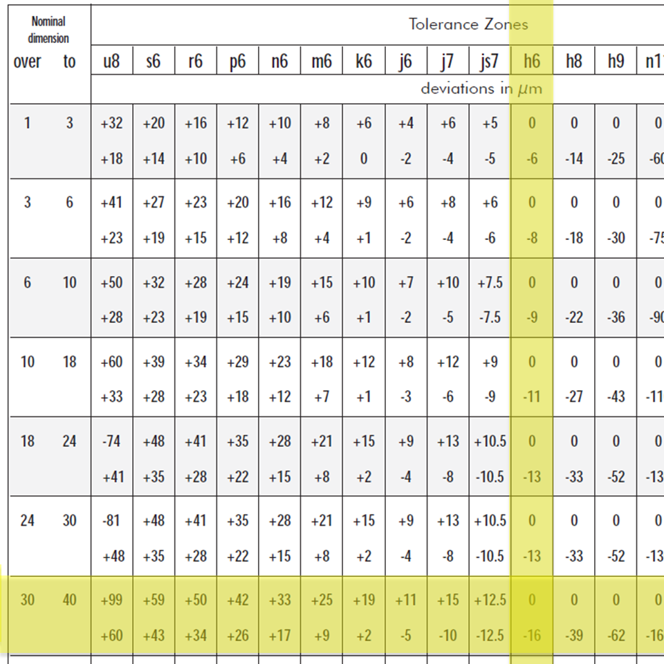
Size limits for Shaft Tolerance Classes h1 - h18. Select Units. Millimeters. Inches. Basic Size. Deviation in microns. Green = "Prefered" tolerance classes. Find your data faster with our Fits and Tolerance Calculator. Basic Size.
Dowel Hole Tolerance H7 Home Interior Design
≥ < b10 c9 d8 e7 e8 f7 g7 h6 h7 h8 js7 k7 m7 n7 p7 r7 s7 t7 - 3 +180 +140 +85 +60 +34 +20 +24 +14 +28 +14 +16 +6 +12 +2 +6 0 +10 0 +14 0 ±5 -10-2-12-4-14-6-16-10-20-14-24-3 6 +188 +140 +100 +70 +48 +30 +32 +20 +38 +20 +22 +10 +16 +4 +8 0 +12 0 +18 0 ±6 +3-9 -12-4-16-8-20-11-23-15-27-6 10 +208 +150 +116 +80 +62 +40 +40 +25 +47 +25 +28.

4 INFO ISO STANDARD H7 2020 * ISOStandard
Shaft and housing tolerances. The fit is determined by the ISO tolerances for shafts and housings (ISO 286) in conjunction with the tolerances Δdmp for the bore and ΔDmp for the outside diameter of the bearings (DIN 620).. Tolerance zones. The ISO tolerances are defined in the form of tolerance zones. They are determined by their position relative to the zero line (= tolerance position) and.
Tolerance Chart For Holes And Shafts
Toleransi adalah suatu penyimpangan ukuran yang diperbolehkan atau diizinkan. Kadang-kadang seorang pekerja hanya mengerjakan bagian mesin yang tertentu saja, sedangkan pekerja yang lain mengerjakan bagian lainnya.. Suaian H8-f7 dan H7-g6. Suaian ini biasanya dipakai pada peralatan yang berputar terus-menerus, misalnya dipakai pada bantalan.

Tabel Toleransi Iso
The following ISO Tolerance Chart for bolts and holes per ISO 286. These size charts do not compensate position or other GD&T location tolerances.
H7 Hole Tolerance A Pictures Of Hole 2018
Nominal Dimension Tolerance Zone in mm (Internal Measurements) over to H7 H8 H9 H11 H13 H14; 0: 1 +0.010 0 +0.014 0 +0.025 0 +0.060 0 +0.14 0 : 1: 3 +0.010 0 +0.014 0 +0.025