
Rangkaian Push Button Arduino
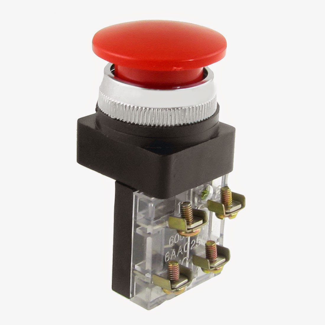
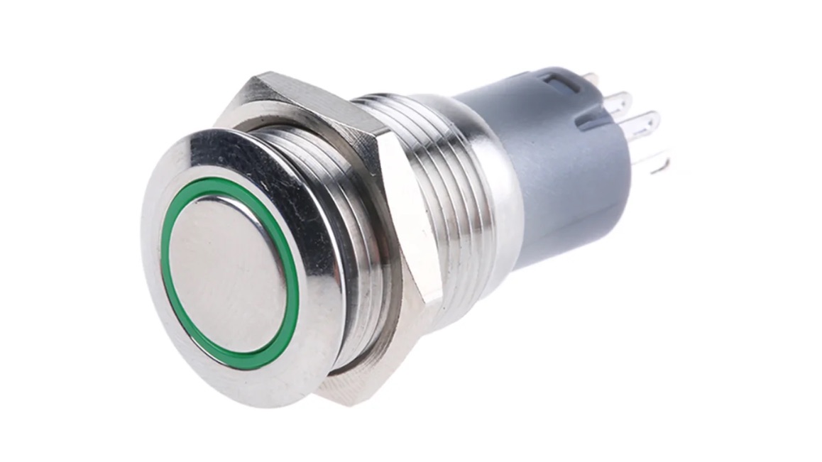
Push buttons, shown in figure 1, are the most common type of control devices found in industrial facilities. Almost all industrial machines contain push buttons even if the facilities operation is to set to run automatically. Typical push buttons are momentary meaning they are designed with a spring to keep the button contacts open or closed at all times. Some push buttons are designed with a.
Push Button Bluino Electronics
The tutorial includes two main parts: Button controls servo motor without debouncing. Button controls servo motor with debouncing. Hardware Required Or you can buy the following sensor kit: 1 × DIYables Sensor Kit 30 types, 69 units Please note: These are Amazon affiliate links.
Mengenal Push Button / Tombol Tekan (Pengantar Praktek Instalasi Motor ListrikIML) Blog edukasi
The schematic symbol for a push button switch is a simple rectangular shape with a line inside, representing the button and the contact points. This symbol is commonly used in circuit diagrams to indicate the presence of a push button switch. It is important to note that the actual physical appearance of a push button switch may vary, as there.

Skema sederhana penerapan Push Button sebagai Switching pada ATMega8535 ELECTROZE vanfams
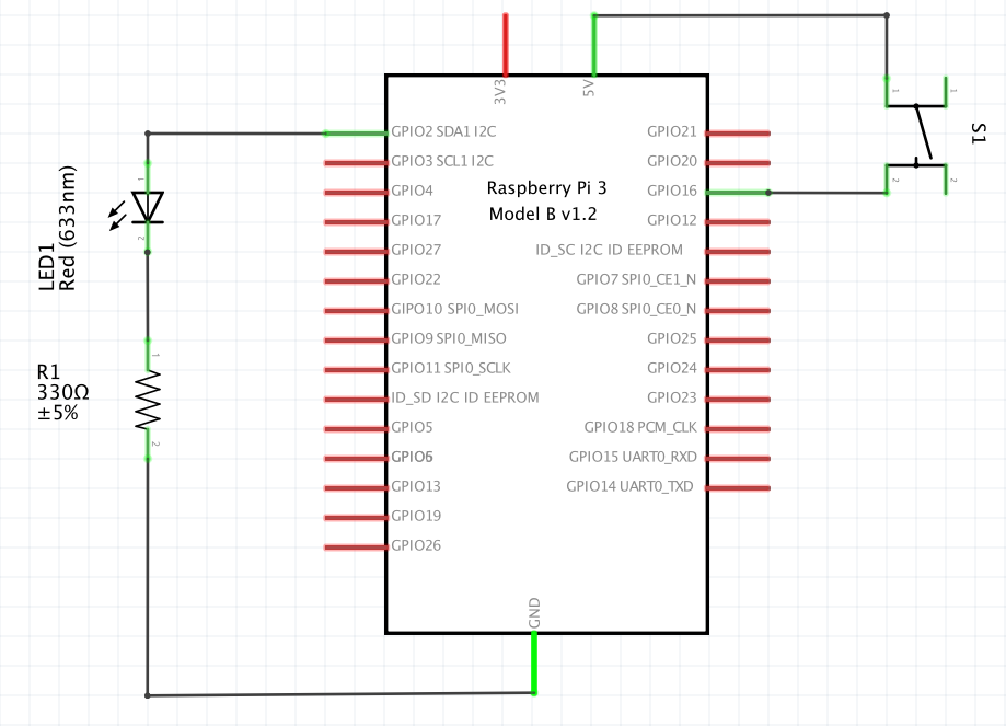
Let us just dive in and see the pin connection. The connection of a button to pin 6 is shown in the image below. Here is an example code for you. Arduino with a push-button on Pin 6. use this link to try it out for yourself! void setup() {. // put your setup code here, to run once: pinMode(6, INPUT_PULLUP); pinMode(13, OUTPUT);

Menyalakan dan Mematikan LED dengan Push Button Arduino Eminence Solutions
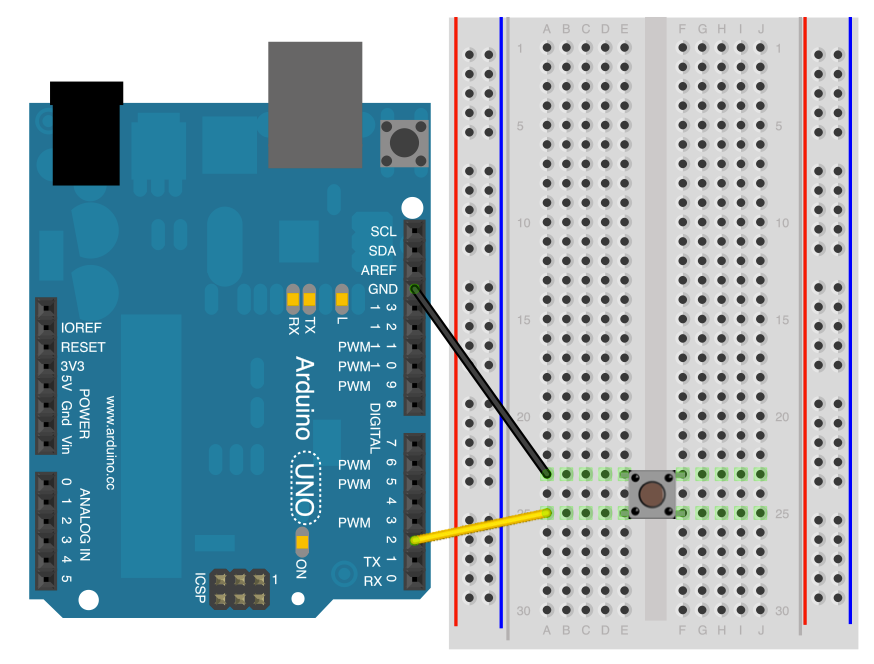
Plug the push button in the middle of the breadboard, like on the picture. On one button's leg, plug a wire (black if possible) to a GND pin on the Arduino board. The top left and bottom left legs of the button are connected together, and the top right and bottom right legs are connected together.

Rangkaian Push Button On Off Brain
Push button adalah komponen elektronik yang digunakan untuk memulai suatu aksi atau memberikan input pada suatu sistem. Tombol tekan sering digunakan dalam peralatan elektronik seperti mesin, otomotif, peralatan audio, mesin cuci dan lain sebagainya.

Cara Kerja Push Button START dan Push Button STOP YouTube
Ø 22 mm plastic push buttons, switches, pilot lights The modular Harmony XB5 range of 22 mm plastic control and signaling units combines simplicity of installation, efficiency, flexibility, modern design and robustness to meet most industrial applications. Bagian dari Harmony Lihat Produk Luncurkan Pemilihan Produk Harmony XB4
Push Button Interfacing with Arduino Reading Digital Inputs
Step 4: Wiring Connections. Push Button connections : The first pin goes from one leg of the pushbutton through a pull-up resistor (here 10K Ohms) to the 5v supply. The second pin goes from the corresponding leg of the pushbutton to Ground ( GND) pin. The third pin connects to a Digital I/O pin (here pin D0) which reads the button's state.
Mengenal Push Button / Tombol Tekan (Pengantar Praktek Instalasi Motor ListrikIML) Blog edukasi
The schematic diagram of a push button switch helps visualize how these components are interconnected and how they function together to control the flow of electrical current. The schematic diagram typically represents each component of the push button switch using specific symbols and lines. These symbols and lines provide a visual.
Skema Push Button
Automatic Door Switches. Hardwire these switches to automatic door openers, electromagnetic locks, and electric strikes and your door will open at the touch of a button or the wave of your hand. Choose from our selection of push buttons, including over 650 products in a wide range of styles and sizes. In stock and ready to ship.

Cara Mudah Menyalakan 4 LED dengan 4 Push Button Menggunakan Arduino UNO Masahen
12mm Tactile Switch Button (momentary push button). Pin names The push button has two set of pins (contacts), 1 and 2. When the push button is pressed, it connects these two contacts, thus closing an electrical circuit. Each contact has a pin of the left side of the push button, and another pin on the right side of the push button.
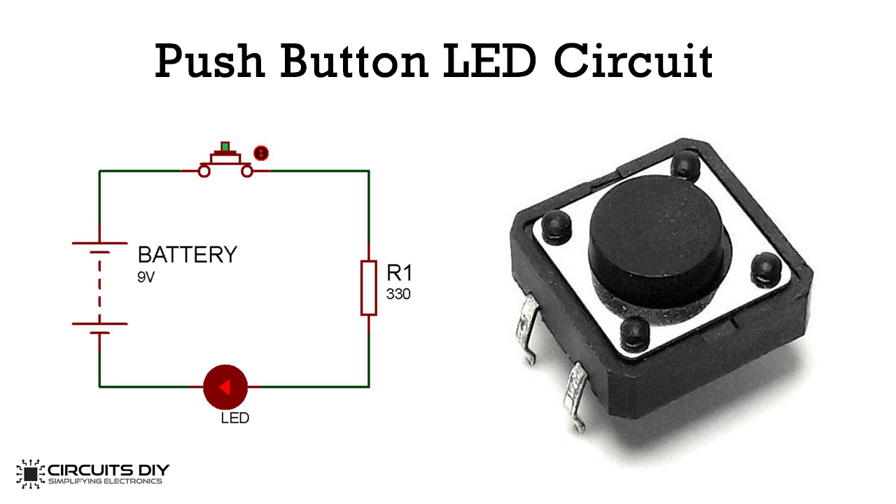
Push Button LED Circuit Basic Electronics
Feb 7, 2021 Setelah minggu lalu kita membuat program blink dengan ESP32 dan Arduino, sekarang kita tingkatkan level kesulitannya menjadi mnambahkan komponen push button dan LED! :) Sekarang apa.

Skema Push Button
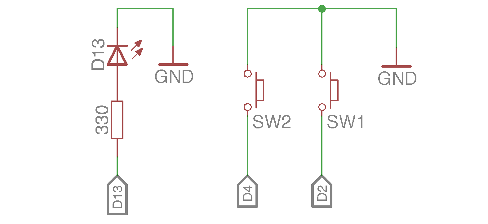
Skema rangkaian push button dengan pull-down resistor Berikut ini adalah gambar simulasi penempatan komponen pada breadboard dan board Arduino. Gambar simulasi ini menggunakan software Fritzing yang bisa didapat di sini. Push buttor for Arduino - Pull-up Resistor

CARA MERANGKAI SISTEM PENGUNCI RELAY DENGAN PUSH BUTTON NO DAN NC YouTube
1) Connect an LED to Arduino Pin 4. 2) Connect the switch to the Arduino. 3) Program the Arduino with the Example Pushbutton Code below. 4) Arduino Simulation for the active-low pushbutton example. Project 2: How To Connect Active-High Push Button To An Arduino.

rangkaian push button on off kontaktor YouTube
Sketch Program Menyalakan LED Dengan Push Button Menggunakan Arduno UNO Sketch Program : const int buttonSaya = 2; // mengubah 'buttonSaya' menjadi variabel pin 2 const int ledSaya = 3; // mengubah 'ledSaya' menjadi cipf-es.org variabel pin 3 int buttonStatusSaya = 0; // mengubah 'buttonStatusSaya' menjadi variable 0
Push Button Switch Pengertian, Fungsi, Jenisjenis (Lengkap)
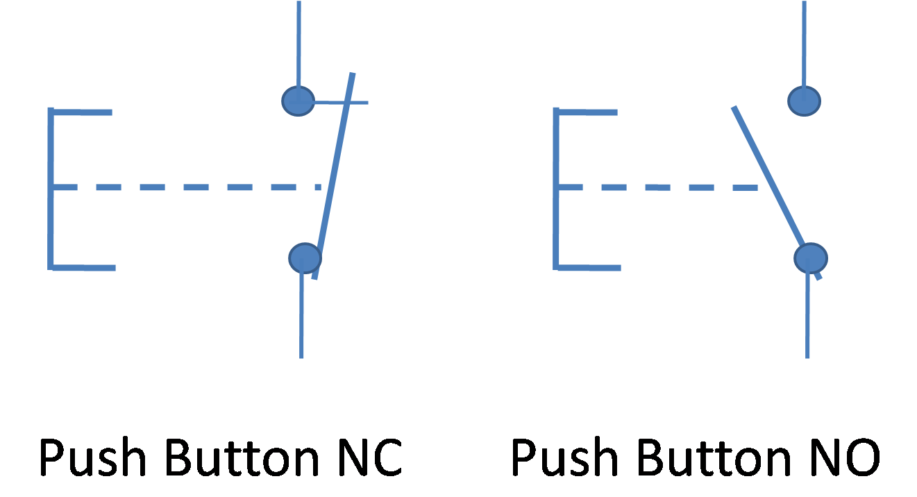
A Push to make or 'Normally Open' (NO) switch is when an electrical flow is activated in a circuit when the button is pressed. And when the button is released the circuit is then broken and the electrical flow is stopped. This is the most common switch type. Whereas a Push to Break switch or 'Normally Closed' (NC) works in the opposite.
