
Circuito inversor para TL494 Subwoofer bricolaje Solar Panel Battery, Solar Panel Kits, Solar
The TL494 device provides for push-pull or single-ended output operation, which can be selected through the output-control function. The architecture of this device prohibits the possibility of either output being pulsed twice during push-pull operation. The TL494C device is characterized for operation from 0°C to 70°C.
Skema Pwm Tl494 Smps 14 Pwm Ic Tl494 Simple smps ferrite inverter youtube sumber. hkidpendidik
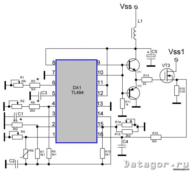
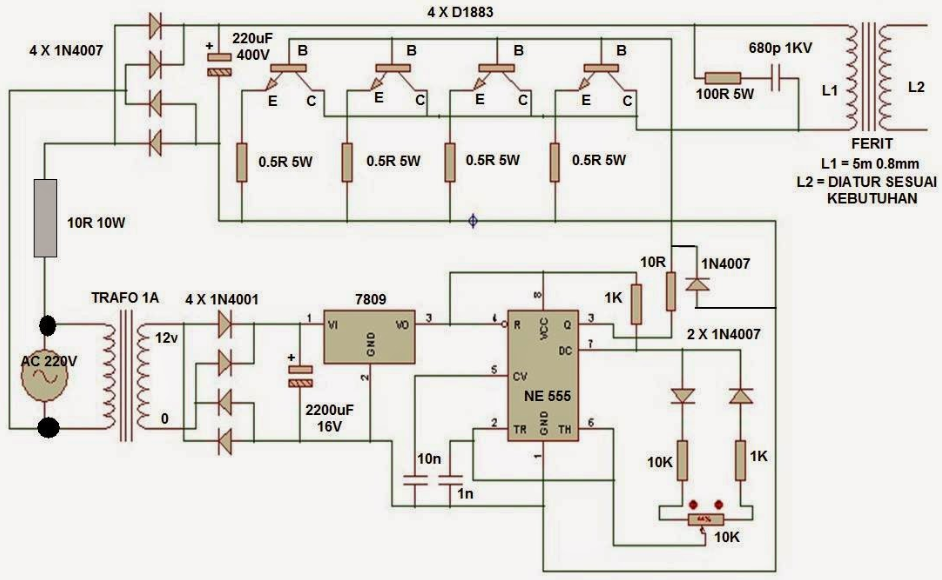
300watts inverter PCB layout. 300w power inverter circuit diagram. The inverter working based on the switching ic of TL494. the ic will generate the high-frequency pulses (about 30khz). The pulses will be amplified by the MOSFET of IRF3205 and pass through the transformer and the Fast diodes will be rectified and give the power output.

Skema Rangkaian Inverter Ic Tl494 / Elektronika Dan Otomotif Skema inverter sg3524 Met kenal
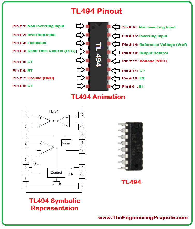
Inverter IC TL494. Now before building the circuit based upon the TL494 PWM controller, let's learn how the PWM controller TL494 works. The TL494 IC has 8 functional blocks, which are shown and described below. The 5V internal reference regulator output is the REF pin, which is pin-14 of the IC. The reference regulator is there to provide a.

High Voltage Power Supply based PWM IC TL494 Power Supply Circuits
bila suka dengan video saya jangan lupa subcribe, like, komen, dan share ya brow..
tl494 ic inverter circuit diagram IOT Wiring Diagram
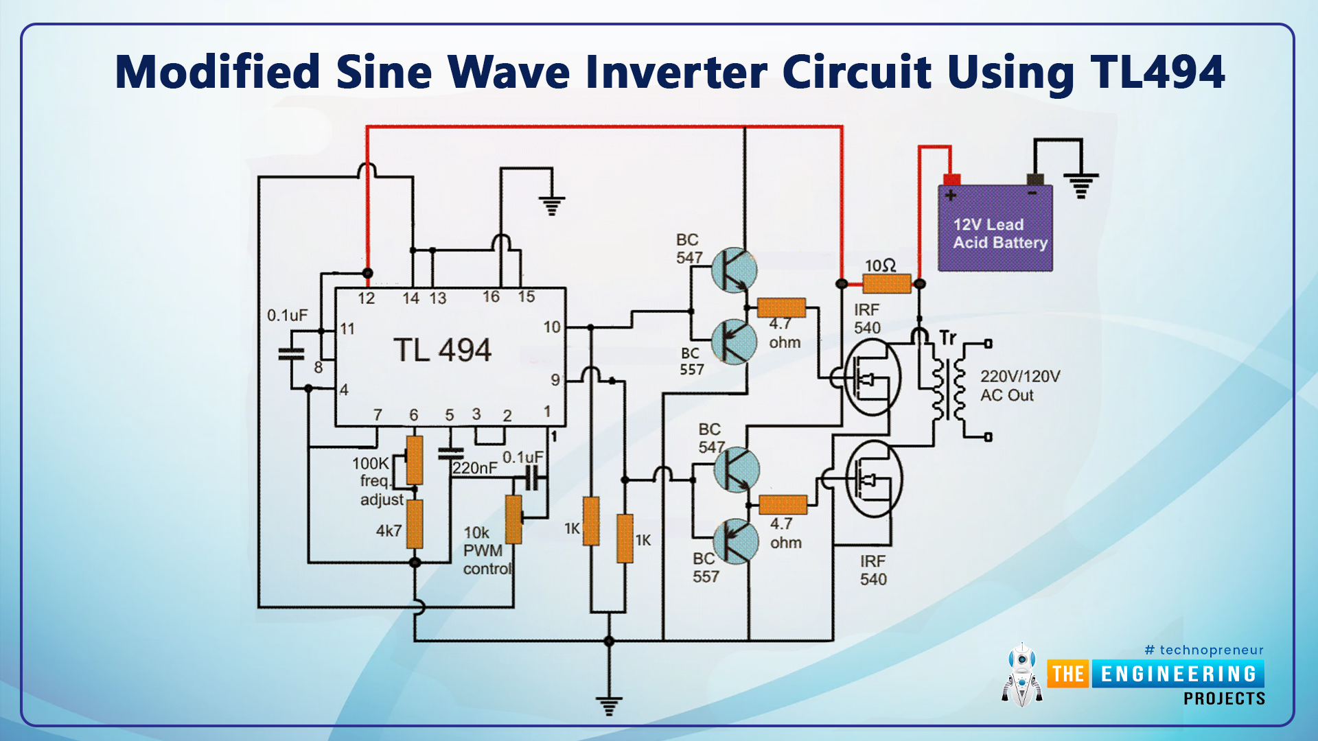
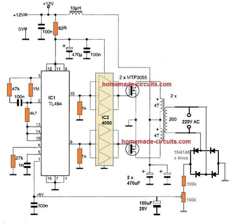
The IC TL494 is a specialized PWM IC and is designed ideally to suit all types of circuits which require precise PWM based outputs. The chip has all the required features in-built for generating accurate PWMs which become customizable as per the users application specs. Here we discuss a versatile PWM based modified sine wave inverter circuit.
Tl494 Pwm Ic Pinout Examples Features Datasheet And Applications Images
Keunggulan dari skema inverter IC Tl494 trafo ferit antara lain efisiensi tinggi, ukuran yang lebih kecil, dan kemampuan untuk menghasilkan tegangan AC yang stabil. Kesimpulan. Dalam artikel ini, telah dijelaskan tentang Skema Inverter IC Tl494 Trafo Ferit. Skema ini menggunakan IC Tl494 dan trafo ferit sebagai komponen utama dalam menghasilkan.

Inverter 12 to +14 on tl494 EasyEDA open source hardware lab
TL494 Pulse-Width-Modulation Control Circuits 1 Features • Complete PWM Power-Control Circuitry • Uncommitted Outputs for 200-mA Sink or. • Solar Power Inverters 3 Description The TL494 device incorporates all the functions required in the construction of a pulse-width-modulation (PWM) control circuit on a single chip..
IC TL494 PWM Modified Sine Wave Inverter Circuit, 52 OFF
About Press Copyright Contact us Creators Advertise Developers Terms Privacy Policy & Safety How YouTube works Test new features NFL Sunday Ticket Press Copyright.
TL494 100W Inverter Circuit Get Vid
To make a stream-lined IC TL494 PWM Modified Sine Wave Inverter, the iron core transformer could be swapped with a ferrite core transformer. The winding particulars for the same could possibly be noticed below: By means of super enamelled copper wire: Primary: Wind 5 x 5 turns center tap, choosing 4 mm (2 2 mm strands wrapped in parallel)
tl494cn circuit diagram Wiring Diagram and Schematics
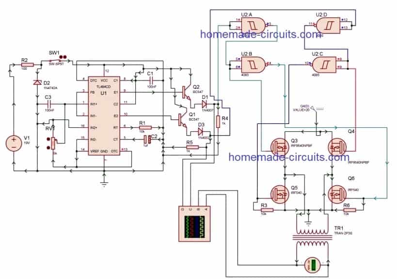
If you're wondering why, join me on this journey. In this project, I'll be creating a simple modified square wave PWM inverter circuit using the popular TL494 chip. I'll explain the advantages and disadvantages of such inverters, and by the end, we'll understand the reasons to avoid making a modified square wave inverter circuit as a DIY project.

Inspirasi 31+ Rangkaian Inverter Ic Tl494, Skema Inverter
The TL494 IC is a fixed frequency current-mode PWM controller IC with all the functions that are required in the construction of the pulse-width modulation. Solar Power Inverters . 2D-Model of TL494. Dimensions for TL3494 IC is given below. These dimensions are for the PDSO package. If you are using a different package IC, please refer to.

18+ Skema Pwm Ic Tl494
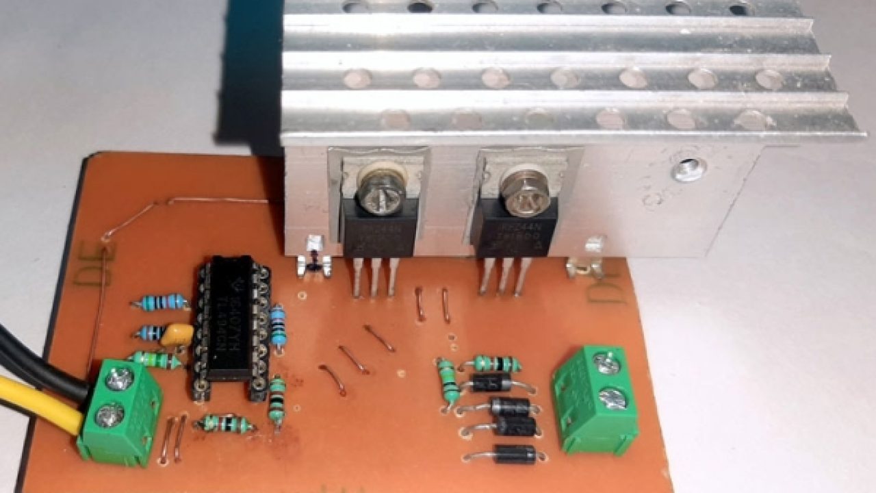
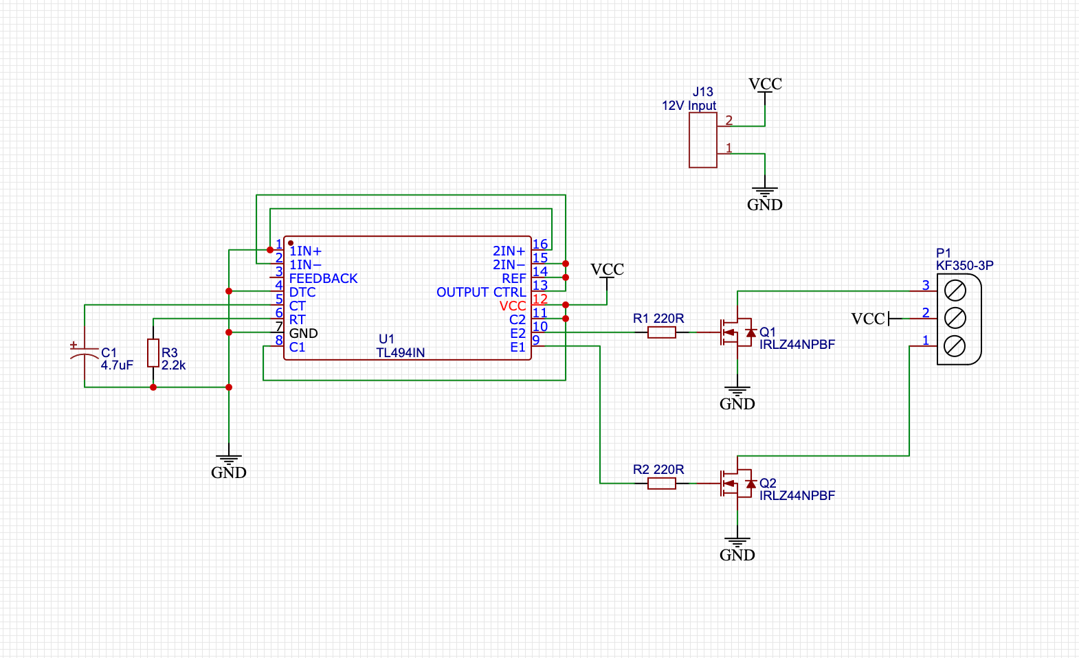
TL494 Inverter Circuit Schematic . TL494CN Inverter Circuit Construction. For this demonstration, the circuit is constructed on a homemade PCB, with the help of the schematic and PCB design files.Please note that if a big load is connected to the output of the transformer, a huge amount of current will flow through the PCB traces, and there's a chance that the traces will burn out.
Ide Rangkaian Inverter Trafo Ferit Skema Inverter My XXX Hot Girl
TL494, NCV494 www.onsemi.com 2 RECOMMENDED OPERATING CONDITIONS Characteristics Symbol Min Typ Max Unit Power Supply Voltage VCC 7.0 15 40 V Collector Output Voltage VC1, VC2 − 30 40 V Collector Output Current (Each transistor) IC1, IC2 − − 200 mA Amplified Input Voltage Vin −0.3 − VCC − 2.0 V Current Into Feedback Terminal lfb − − 0.3 mA Reference Output Current lref − − 10 mA

SKEMA INVERTER IC TL494 YouTube
Overall, the TL494 IC is a practical PWM control circuit that gives you accurate feedback and output control. Its facilities also ensure you get the perfect pulse control for any PWM application. Additionally, the TL494 is quite similar to the SG3525. Plus, you can also use it as an alternative.
tl494 ic inverter circuit diagram IOT Wiring Diagram
The IC TL494 is a versatile PWM control IC, which can be applied in many different ways in electronic circuits.. sir this tl494 inverter and CD4047 inverter which one is more better. Reply. Swagatam says. January 4, 2023.. The 18v ac trafo is wired with a fwbr but also utilizes a half wave rectified subcircuit on one ac input and it ramps.

Pwm inverter using ic tl494 circuit homemade circuit projects Artofit
The TL494 IC is a fixed frequency current-mode PWM controller IC with all the functions that are required in the construction of the pulse-width modulation (PWM) control circuit on a single chip. This article will introduce TL494 systematically from its features, pinout to its specifications, applications, and so much more.
