Ladder Logic Symbols All PLC Diagram Symbols
A flexible PLC module that generates into any module. The Programmable Logic controller symbol contains smart tools that will allow you to generate symbols quickly without the need for much typing, reducing your workload and improving your productivity. Find out how you can generate your own custom PLC symbol easily. Symbols that understand.

Simbol Asas PLC PDF
PLC Symbol Meaning is an important part of using programmable logic controllers. Understanding these symbols is key to being able to design and operate a PLC system. There are a wide range of symbols used in PLCs and each one has its own set of meanings. Some common symbols include input/output (I/O) boxes, ladder diagrams, Boolean logic.
Perintah Dasar Pemrograman PLC CX Programmer 3 Samrasyid
By energizing the bit that is tied to the output, a PLC programmer can change the state of the output to the desired position. 1. Turn ON Light / Output. Ladder Logic Symbols - Light Seal In Logic in Studio 5000. In the rung above that we've already seen, the output is energized when the conditions are met.
Kelistrikan Pengertian dan Simbol PLC
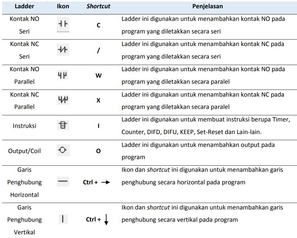
Simbol Dasar Ladder diagram PLC. By Mata Kuliah Teknik. 1. LOAD / LD merupakan instruksi bagian paling kiri yang langsung tersambung ke pegangan tangga sebelah kiri dan dalam keadaan terbuaka atau Normaly Open (NO). 2. LOAD NOT / LD NOT merupakan instruksi bagian paling kiri yang langsung tersambung ke pegangan tangga sebelah kiri dan dalam.

Simbol Dasar Program PLC Ladder Logic NO, NC, AND, OR, OR NOT, AND XOR YouTube
SIMBOL SIMBOL DASAR PROGRAM PLC| PROGRAM PLC

PLC Simbol dan fungsinya....
In IEC 61131 the percent symbol means it refers to an a fixed hardware address. Eg: input/output or some other feature of the PLC hardware. These addresses may never change, regardless of program size. In contrast to other variables that the compiler may put anywhere within the specified retention area.
Info plc simbologia
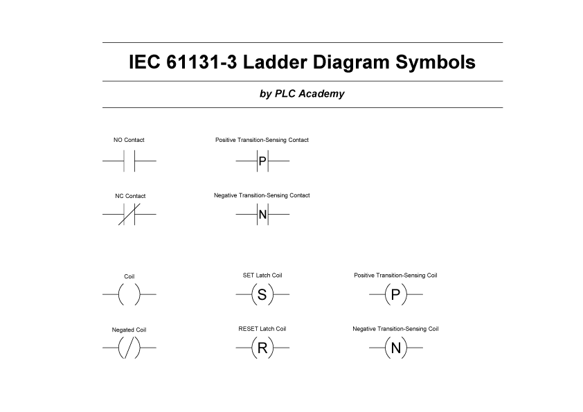
PLC Basics. Ladder Logic Symbols - All PLC Ladder Diagram Symbols. by peter June 28, 2015. 10. Ladder logic symbols are the basic building blocks for ladder diagrams. Right here you will find all the ladder diagram symbols which are described in IEC 61131-3. The symbols are available for download in all formats and in a PDF-file.
PPT INTRODUCTION TO PLC PowerPoint Presentation, free download ID6156871
PLC (Programmable Logic Controller) ladder diagram is a graphical programming language used to program industrial automation processes. It is widely used in industries for monitoring and controlling various operations. To effectively understand and write PLC ladder diagrams, it is essential to have a good understanding of the symbols used in.
Plc Logo DWG Block for AutoCAD • Designs CAD
kelasplc. April 23, 2022. Simbol Ladder Diagram PLC - Simbol simbol ladder diagram yang di gunakan dalam pemrograman ladder diagram sebenarnya mirip dengan sirkuit kontrol logika relai tradisional. Jika Sahabat memiliki pengetahuan dasar tentang rangkaian listrik maka memulai pemrograman dengan bahasa pemrograman Ladder diagram sangatlah mudah.
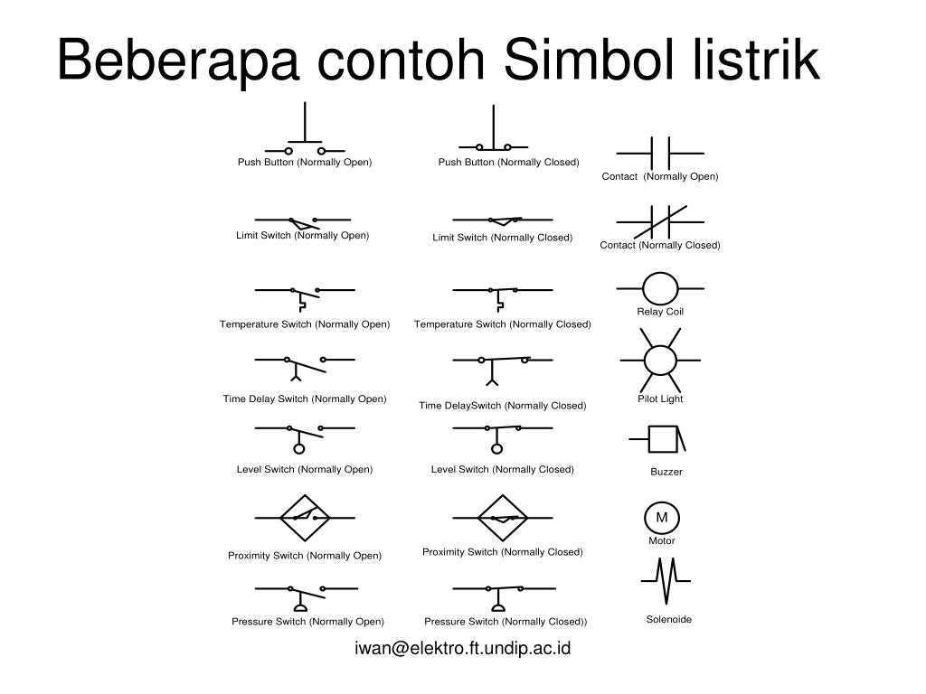
Simbol simbol listrik1
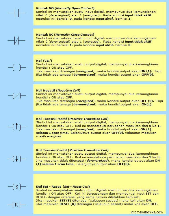
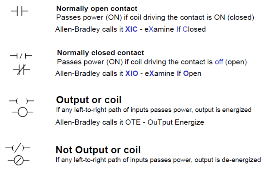
In ladder logic the normally open contact (NO) and normally closed contact (NC) symbols are mainly used to define PLC digital inputs and internal logic instructions. They have been translated into ladder logic from switches and relay contacts used in electric circuits. An coil in ladder logic is the symbol which mainly defines PLC digital outputs.

Plc Symbols And Meanings
Simbol says the plant will have the capacity to produce 15,000 metric tons of lithium annually. The permits are ready, Mr. Burba said, and Simbol has secured the water necessary to operate the.
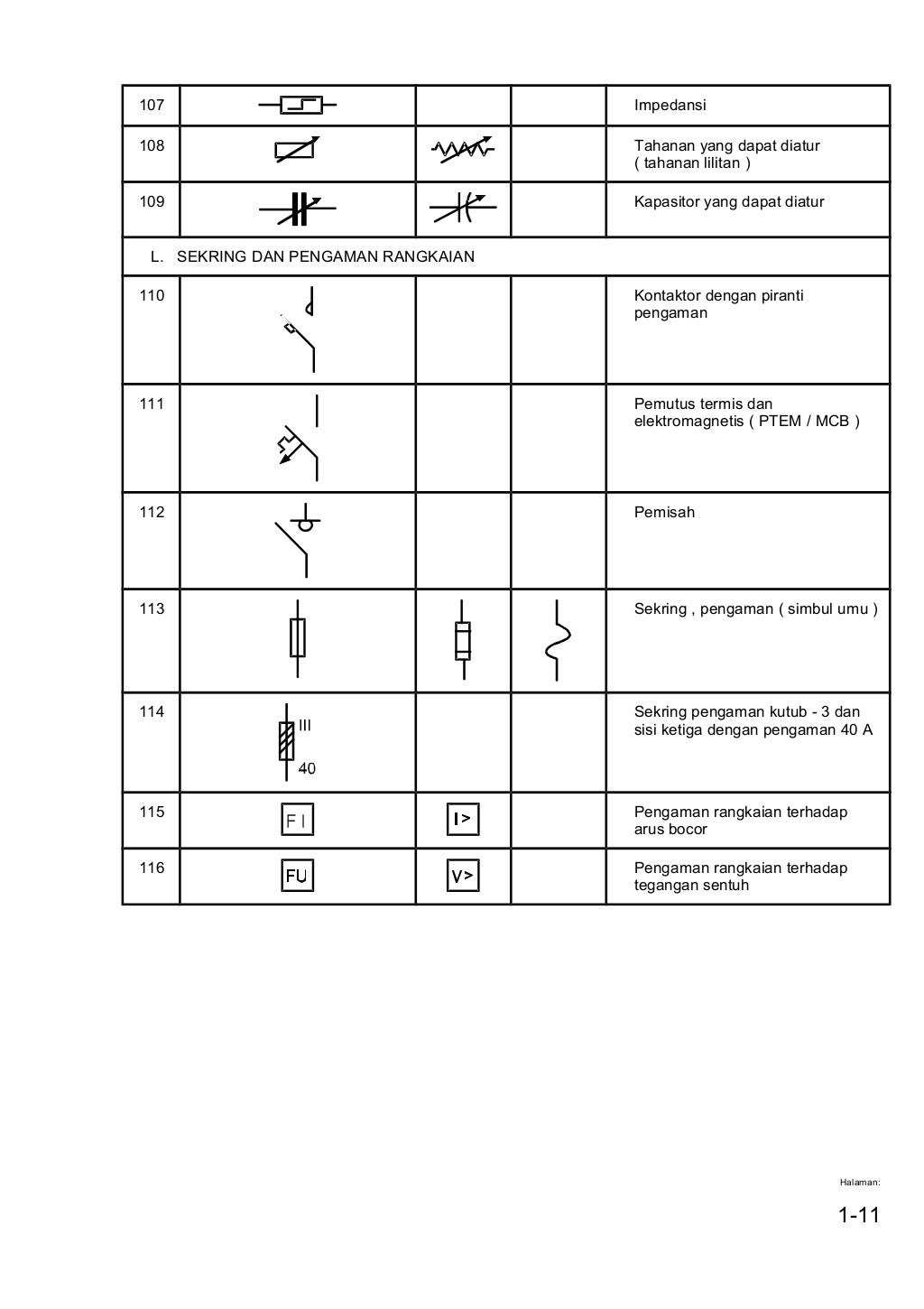
Simbol simbol listrik1
All the ladder logic symbols or PLC programming instruction available in the format of bit Logic , Arithmetic, Logical, Counters and Timers etc. and data size will be defined in byte, Word, DWORD based on type of Ladder Logic Symbol. In this tutorial we will discuss Bit logic instructions one by one. So lets start….
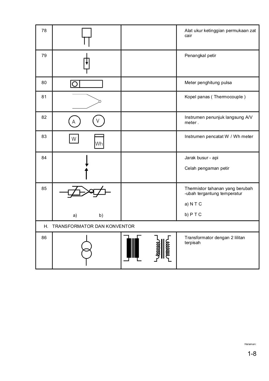
Simbol simbol listrik1
Ladder logic (also known as ladder diagram or LD) is a programming language used to program a PLC (Programmable Logic Controller). It is a graphical PLC programming language which expresses logic operations with symbolic notation. Ladder logic is made out of rungs of logic, forming what looks like a ladder - hence the name 'Ladder Logic'.

PLC 'Summary' Symbol Autodesk Community
Summary. Let's review what we've discussed today: - DCS and PLC symbols became a necessity with the computerization of process automation. - If you see a square box drawn around the circle on a P&ID, that means a DCS is part of the control process. - If you see a square with a diamond in it on a P&ID, that means a PLC is part of the.
PLC
Some of the more common types of PLC symboleanings include: Inputs (rectangle): used to represent digital inputs, such as switch closures and voltage levels. Timers (diamond): used to represent time-based operations, such as time delays and pulse widths. Counters (triangle): used to represent count-based operations, such as cycle counts and.
PLC Programming Basics using Ladder Logic Learn Robotics
The PLC (Programmable Logic Controller) is largely divided into the basic commands, function commands and exclusive commands, and ample command types are available. The commands can be used according to the purpose and application such as the PLC
