Free download Electric current Current transformer Electronic symbol Wiring diagram, symbol
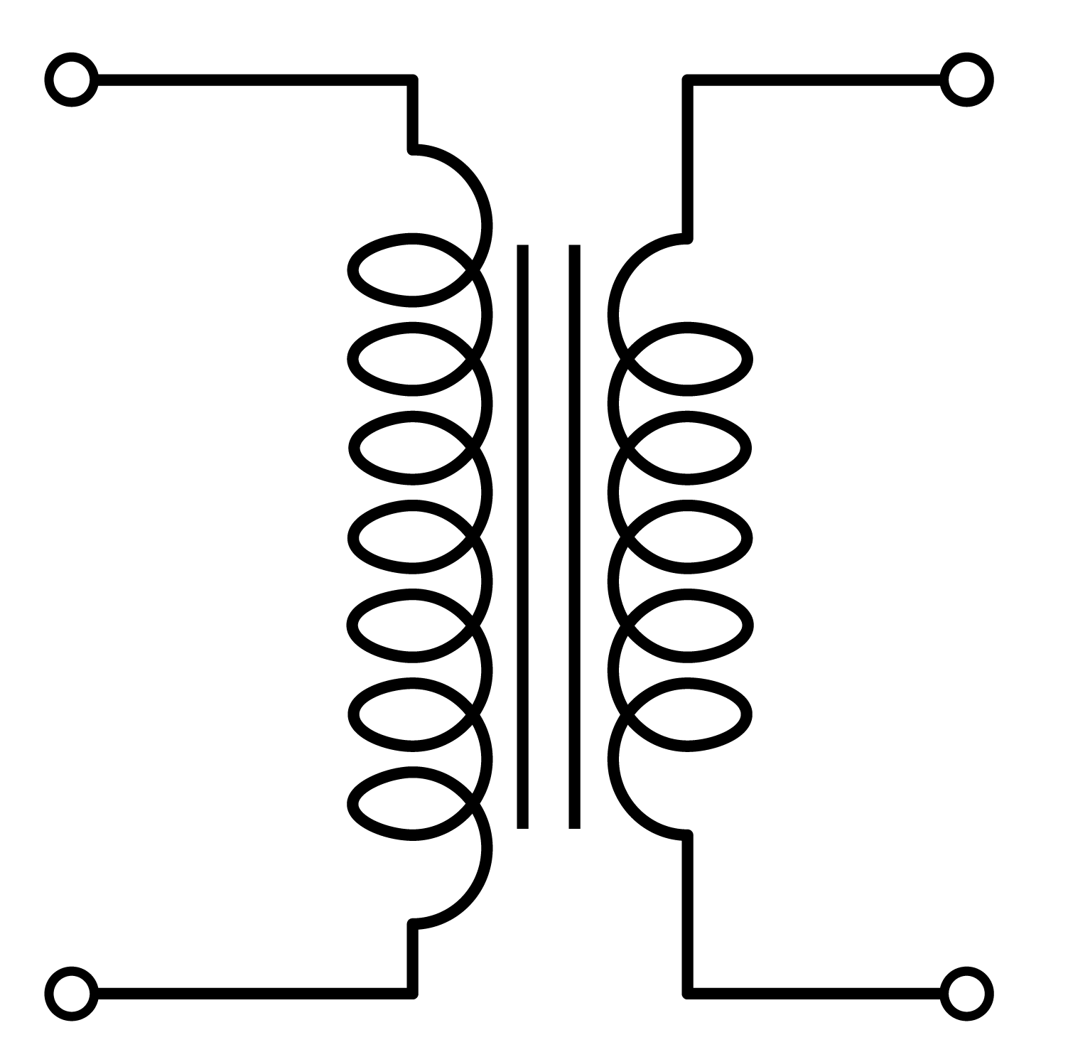
Electrical Transformer Symbols. The electrical transformer is a component consisting of two or more coils coupled by magnetic induction. It is used to transfer electrical energy, and to increase or decrease the tension in an AC circuit, keeping the frequency. The autotransformer has only one winding. Electrical transformer.

Electrical Symbols 12 Electrical symbols, Electricity, Current transformer
Definition of Current Transformer. A current transformer is a device which is used for the transformation of current at a higher value to a lower value with respect to the earth potential. It is used with the AC instruments for measuring the high value of current. The line current is too high, and it is very difficult to measure them directly.
Ultimate Guide To Current Transformers What are Current Transformers
The zig zag configuration provide a neutral for grounding or for supplying a single phase load. Following is the list of single line transformer symbols. Transformer Symbols - Single Line Transformer Symbols - Autotransformer & CT, Star Delta & 1 Phase & 3 Phase Transformer. Step-up/Step-down Transformer.
Transformer symbols
The Current Transformer ( C.T. ), is a type of "instrument transformer" that is designed to produce an alternating current in its secondary winding which is proportional to the current being measured in its primary.Current transformers reduce high voltage currents to a much lower value and provide a convenient way of safely monitoring the actual electrical current flowing in an AC.
Electrical Diagrams and Schematics Inst Tools
Protective relays connected to current transformer: Device numbers indicate types of relays connected, such as: • 67 - Directional overcurrent • 51 - Time overcurrent: Simple electrical circuit. Now, that you are familiar with electrical symbol, let's look at how they are used in interpreting single line diagrams.
Electric symbols set of current, threephase connections and electrical transformers Stock ベクター
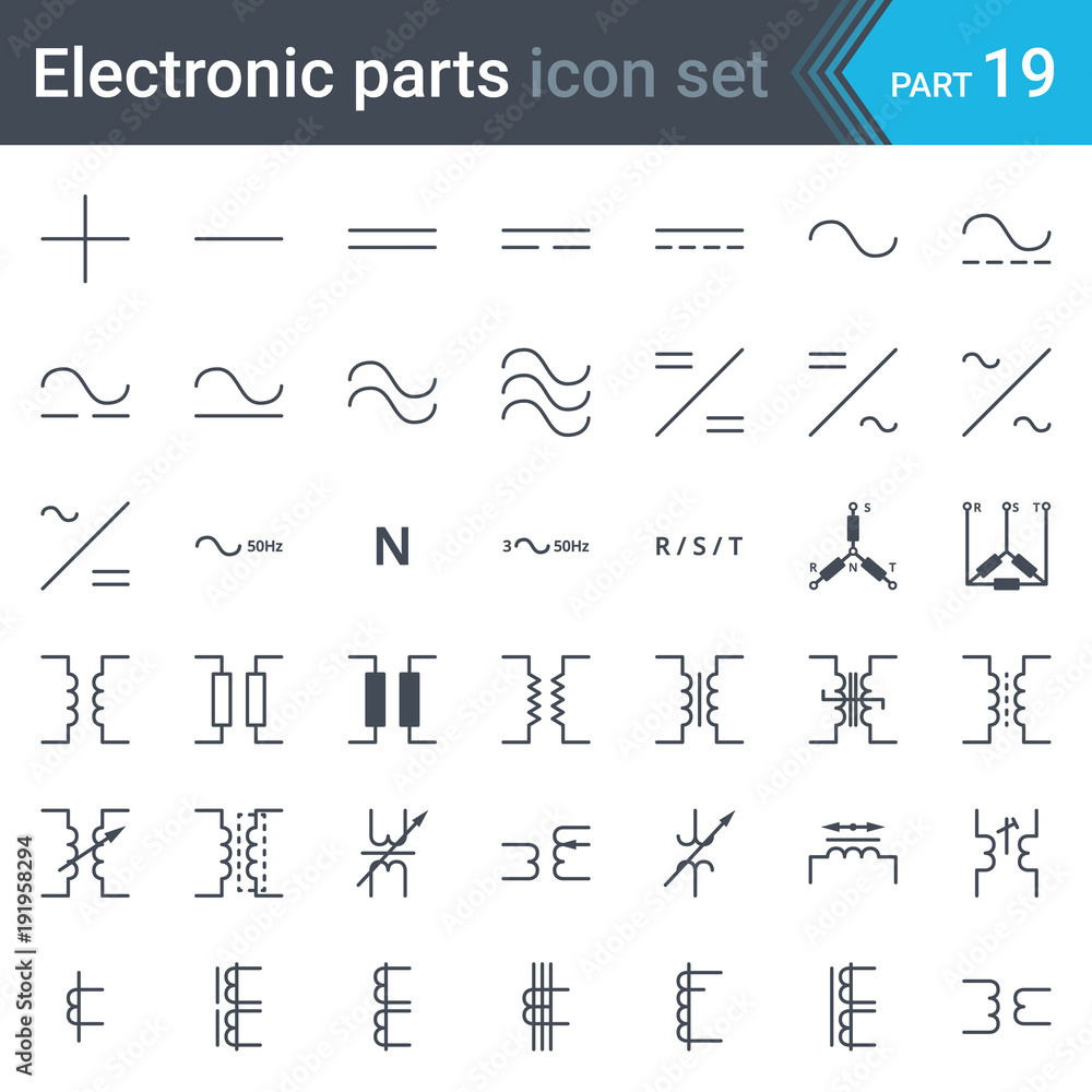
The following transformer symbols show some standard electrical transformer symbols for industrial control systems such as magnetic core symbol, inductor symbol, choke symbol, variometer symbol, transductor, induction, induction voltage, current transformer, linear coupler symbol, etc. Every transformer symbol can be configured by the action.
Electrical Transformer Symbols Single Line Transformer Symbols
Single Line Representation. The electrical transformer is a component consisting of two or more coils coupled by magnetic induction. It is used to transfer electrical energy, and to increase or decrease the tension in an AC circuit, keeping the frequency. The autotransformer has only one winding.
Current Transformer Classification based on Four Parameters
A transformer is an electrical device that transfers electrical energy between two or more circuits through electromagnetic induction. Electromagnetic induction produces an electromotive force within a conductor which is exposed to time varying magnetic fields. Transformers are used to increase or decrease the alternating voltages in electric power applications.
26 libraries of.
[DIAGRAM] Electrical Transformer Wiring Diagram Symbols
Symbol Description Notes; Name: Current transformer, general symbol. Form 1. Alternative name: Pulse transformer Source: IEC 60617-2019, IEEE Std 315-1993 A1, A2: Name: Current transformer, general symbol. Form 2. Alternative name: Pulse transformer Source: IEC 60617-2019, IEEE Std 315-1993 A1, A2, A4, A5: Name: Current transformer with two cores with one secondary winding on each core.
Electrical Symbols Transformers and Windings
Since transformers are not transparent, it is impossible to know which way to connect a circuit to it to get an in-phase (or out-of-phase) voltage and current, thus, to mitigate the risks associated with reverse polarity connection and phase loss, and provide a way of identifying the polarity of the windings, transformer manufacturers came up with a polarity indication standard called; the.
Transformer Symbol ClipArt Best
Single line symbols electrical symbols used to represent various electrical devices for usages in electrical schematic design. Tip: Streamline your electrical design process and improve your workflow with Capital Electra X. It offers a powerful and user-friendly solution for electrical schematics, making your design tasks fast and easy.
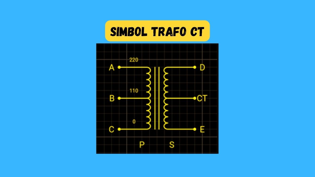
√ Trafo CT Fungsi, Jenis, Simbol, Cara Kerja, Pasang
Construction of the Transformer. Basically, a transformer is made up of two parts which include; two inductive coils and a laminated steel core. The coils are insulated from each other and also insulated to prevent contact with the core. The construction of the transformer will thus be examined under the coil and core construction.
Basic Electricity and Electronics Inductors
In a three-phase transformer, the core has three legs with three primary windings and three secondary windings. Further three phase transformers have multiple types depending on how we connect the primary and secondary windings (Star - Delta, Delta - Star, Star - Star, Delta - Delta, etc.). Isolation Transformer: The main job of an.
Electrical Transformer Symbols Single Line Transformer Symbols
Current transformers may be shown in several formats as indicated in Figure 6 below. The dots, X's or boxes are used to denote the instantaneous polarity orientation of the CT. The polarity marks on the conductor generally face toward the source of the current flow. The polarity mark on the CT winding represents the relationship of the CT's.
IEC and NEMA/IEEE ratings of current transformers (CTs) in medium voltage applications EEP
9. The dots tell you the relative orientation of the windings. Without them, you don't know the polarity of the voltage coming out of the secondary with respsect to the primary. In many transformer applications that doesn't matter, but when it does the dots need to be shown on the schematic. The way to read the dots is to imagine current going.
Electrical Symbols Transformers, Generators CAD Block And Typical Drawing For Designers
With 2 Secondaries - Independent Magnetic Circuits : HXF1T31. VXF1T31
