Water Level Controller using 8051 Microcontroller
https://www.kitszone.com/2019/01/newfully-automatic-water-level.html#moreFully Automatic Water Level Controller Circuit Diagram With Dry Run Protection And W.

Fully Automatic Water Level Controller with Dry Run Protection and 1 Year Warranty. Amazon.in
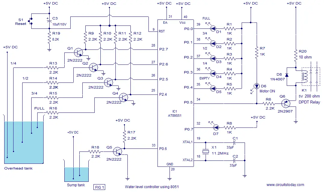
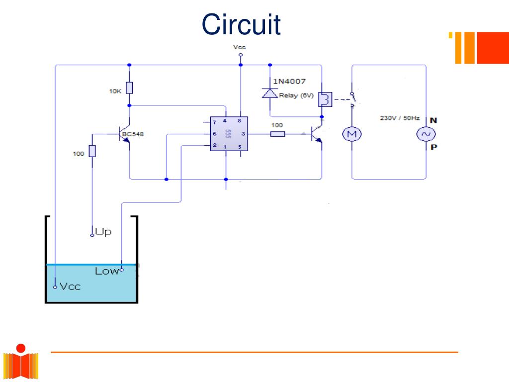
CIRCUIT DIAGRAM Fig. 2 Circuit Diagram WORKING OF CIRCUIT: The operation of project is very simple and can be easily understood. In our project "Automatic water controller" there is three main conditions: 1. There is no water available in the water tank (Vcc). 2. Inter mediate level (Low). 3. There is ample amount of water available in tank.
Electrical and Electronics Engineering Water level controller circuit diagram
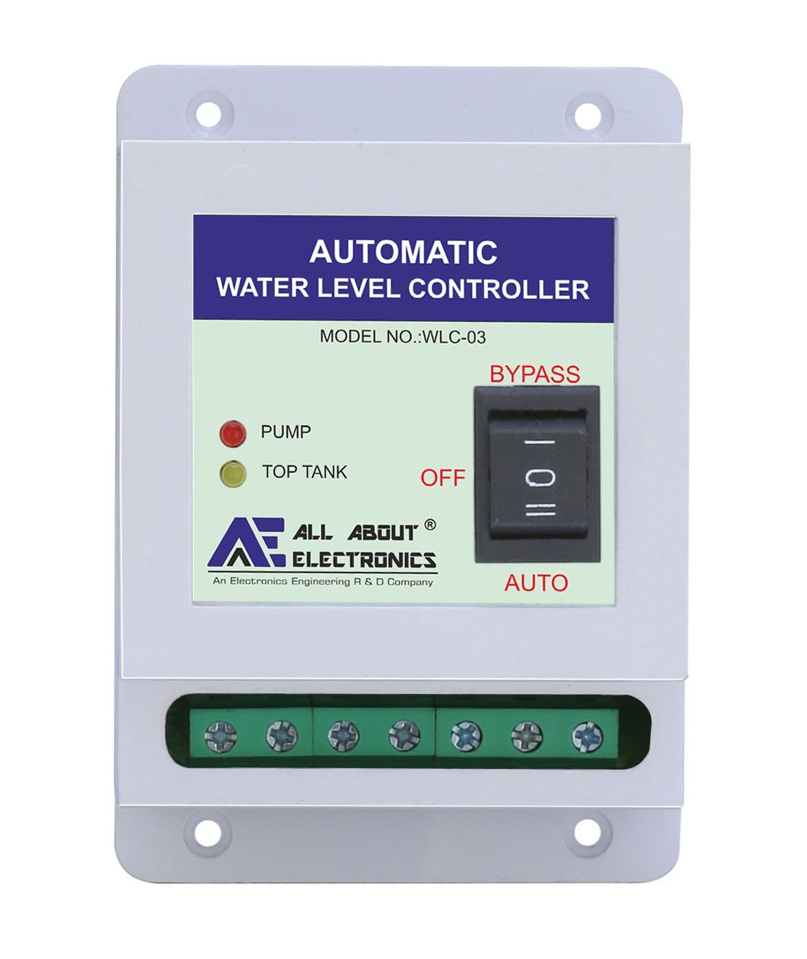
Automatic water level controllers are a product that was created to automatically control a motor, which helps to ensure a constant reserve of water in a storage tank. These automatic water level controllers are used to automatically fill the over-head tank when it starts or has become empty as well as monitor the water level in it.

Intelligent Overhead Tank Water Level Indicator The project is designed to give a display of w
In this 555 project, I have explained how to make an automatic water level controller for submersible pump using the 555 timer IC. This water pump controller will also check the water level in the underground tank and automatically ON and OFF the pump according to the water level in the overhead tank.

Full Automatic Water Level Controller using SRF04, L293D & PIC16F84A
Explanation of circuit: The ultrasonic sensor is connected to digital input pins of Arduino. Arduino shows the status of motor and water level on the 16 x 2 LCD. If the water level decrease to below 100 centimeters, the motor turns ON. When the level of water becomes more than 40 centimeters microcontroller automatically turns OFF the motor.
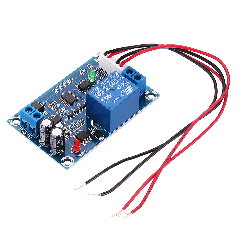
XHM203 AC/DC 12V 10A Automatic Water Level Controller Water Level Switch Liquid Level Pump
The water level controller circuit is a simple mechanism to detect and control the level of water in the overhead tank and also in the other containers. Nowadays, all the householders/owners are storing the water in overhead tanks by using the pumps.
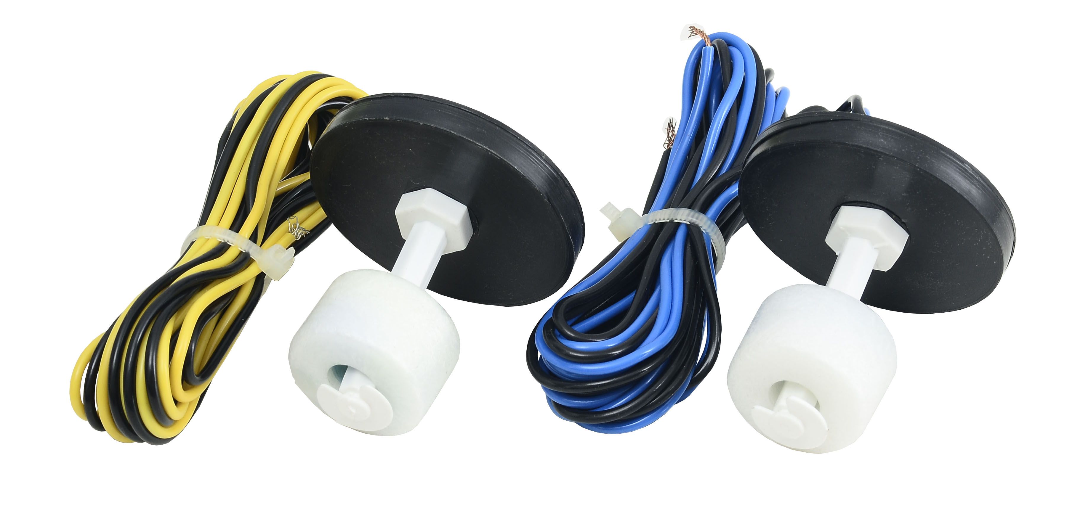
Buy Best Quality Fully Automatic water level controller with float corrosion free
The circuit is connected to a 12 VDC source, but the voltage can be changed to 9 VDC without problems. If it does, the relay must be replaced by a 9V one. Automatic Water Level Controller that ensures that an elevated tank always has enough amount of water. Perfect for 2 or more stories buildings or houses.

Joy Automatic Water Level Controller for Sump, Screw at Rs 5000/piece in Coimbatore
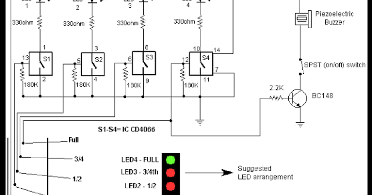
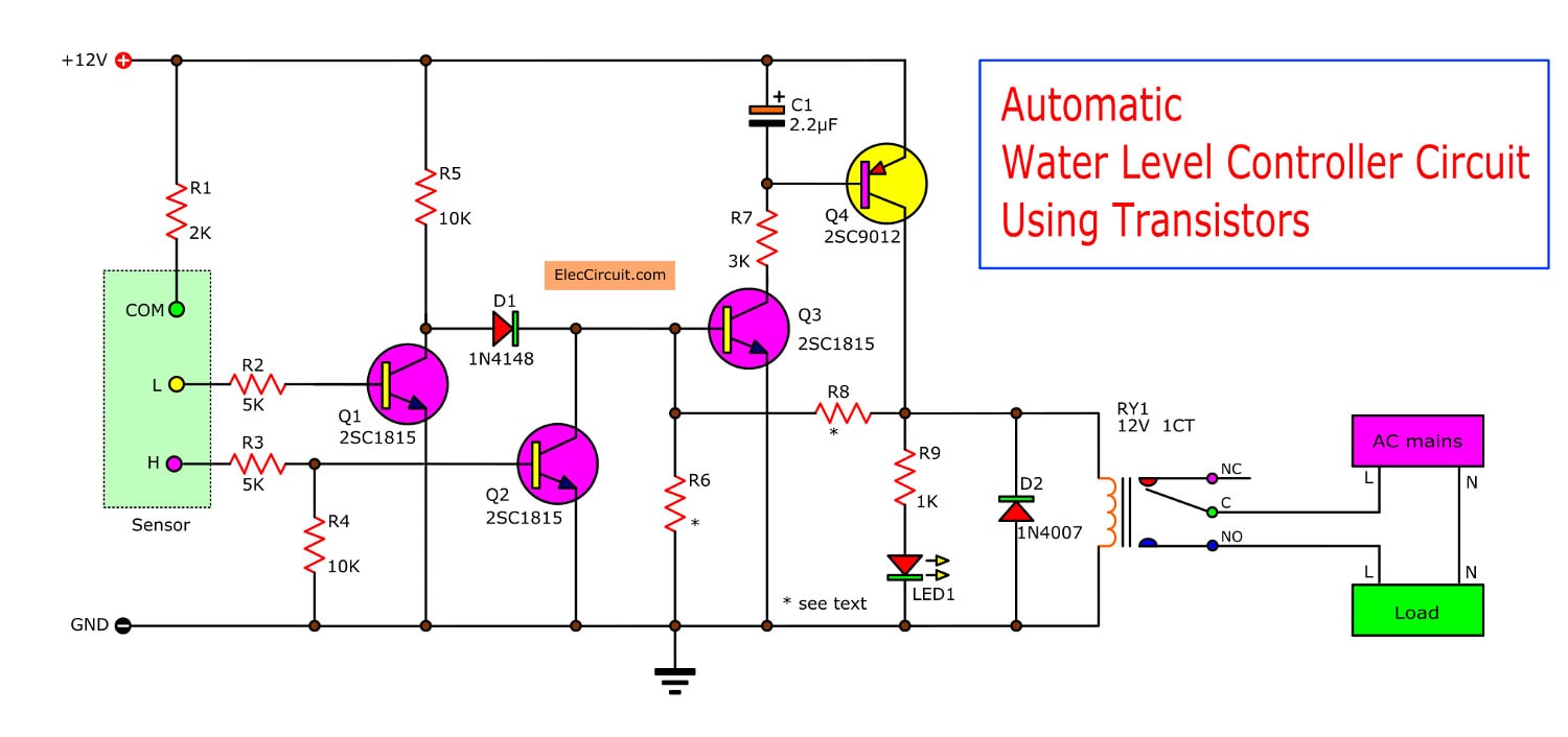
Water Level Indicator Circuit Diagram and Sensor Arrangement. Water Level Indicator. This is the most basic form of water level indicator used for measurement. If you need a fully automatic water level controller circuit then try this circuit Water level controller. The circuit is fully based primarily on transistors.
Automatic water level controller circuit project
yeah there is a way just using a Ultrasonic sensor, this is very simple where the level of water is measured using ultrasonic sensor which gives the depth , by determining the tank depth we can set the maximum and minimum level Step 1: Circuit Diagram This water level controller uses only two components apart from arduino 1.

Joy Automatic Water Level Controller for Borewell, Screw at Rs 4500/piece in Coimbatore
Circuit Operation When the water level touches probe H, transistor T3 gets forward biased and starts conducting. This causes reverse biasing of transistor T4 and it gets cut off. As a result, the relay de-energises and the pump stops. Transistors T4 and T6 will be turned on again only when the water level drops below the position of L probe.
3 phase water level controller circuit diagram Wiring Diagram and Schematics
This article is a about a fully functional water level controller using Arduino. The circuit displays the level of water in the tank and switches the motor ON when the water level goes below a predetermined level. The circuit automatically switches the motor OFF when the tank is full.
PPT AUTOMATIC WATER LEVEL CONTROLLER PowerPoint Presentation, free download ID2401400
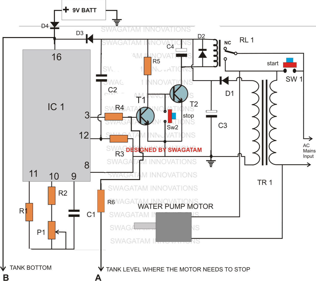
Automatic Water Pump Controller R. Aravind & V. Pradeep Kumar November 10, 2023 118372 - Advertisement - Here's an automatic water pump controller circuit that controls the water pump motor. The motor gets automatically switched on when water in the overhead tank (OHT) falls below the lower limit.
Water level controller cum indicator circuit diagram
Circuit Diagram of Automatic Water Level Controller Click image to enlarge Figure 1: Water Level Controller Parts Description The following components would be used for designing the circuit. Ultrasonic Range Finder SRF04 PIC Microcontroller PIC16F84A Motor Driver L293D DC Motor Two 1K Resistors Let us have a brief idea about each component
Buy Best Quality Fully Automatic water level controller with float corrosion free
Minilec WLC D1 Water Level Controller connection Diagram provide to Learn About fully automatic water level controller circuit Auto manual wiring diagram | w.
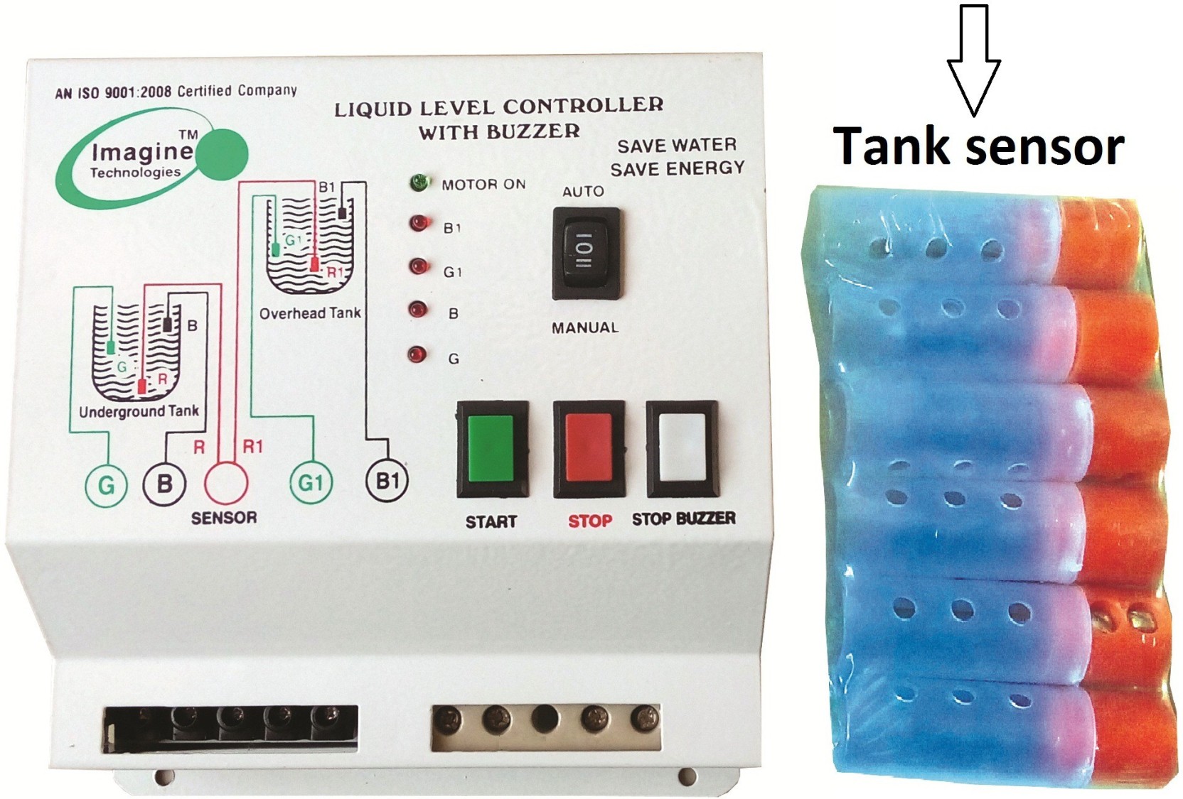
Imagine Tech Fully Automatic Water Level Controller with Indicator& Buzzer Wired Sensor Security
Fig. 1: Simple automatic water level controller. The circuit works off a 12V battery or 230V AC mains using a 12V adaptor. The three sensors built from non-corrosive metal are fitted to the OHT as shown in Fig. 2 and connected to the circuit (Fig. 1) at appropriate terminals. Power supply terminal Vcc is at the bottom of the tank, sensor.

Automatic water pump control in water level controller with contactor YouTube
This video shows a Fully Automatic Water Level Controller Wiring Diagram. This water level controller will use two components: an ultrasonic sensor and a relay board. A distance.
