audio mixer schematic Wiring Diagram and Schematics
This audio mixer circuit is built by assembling the following components: Power supply - The pre-amp for the microphone requires a 5V DC and the power amplifier is powered by a 9V DC in the circuit. Smartphone - To receive audio from the smartphone, a 3.5 mm audio jack must be plugged into it. The jack should have three wires: one to ground.
audio mixer circuit Audio Circuits Next.gr
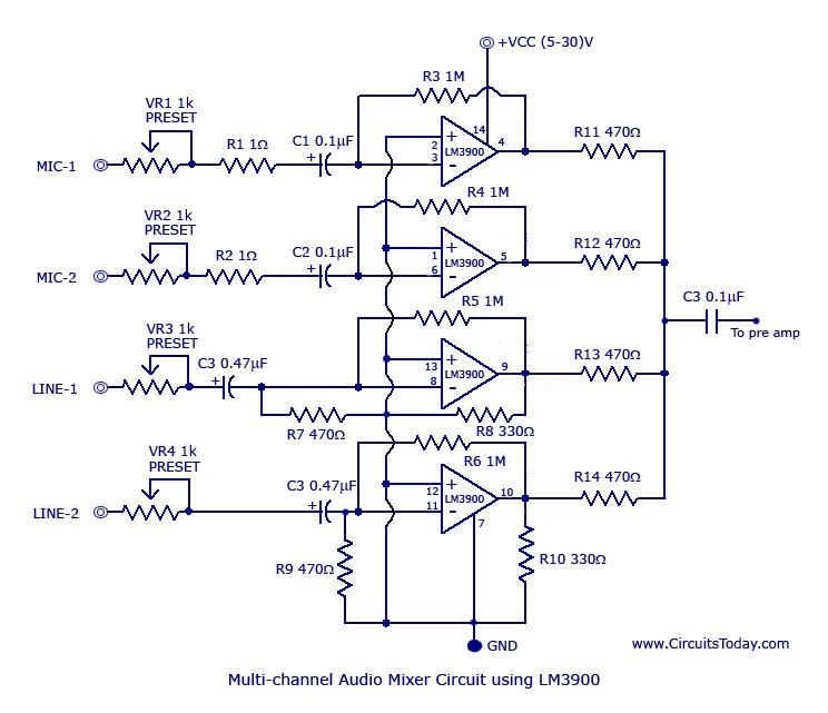
This audio mixer circuit can be powered between 5 to 30V. If the supply circuit is far from audio mixer circuit then connect a 100uF/60V capacitor between supply and ground pins. Multi Channel Audio Mixer Circuit Features: Wide supply voltage range; Low input current (30nA) Open loop gain is very high; simple design; Good frequency response.

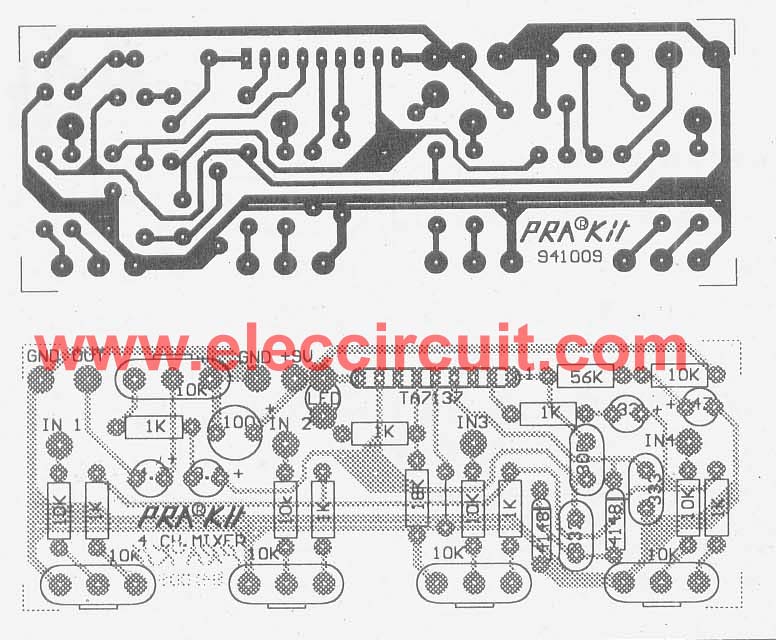
Audio Mixer Circuit Diagram With Pcb Layout Disco Audio Mixer Circuit » Pcb
This is a tutorial on how to build your own 5 Channel passive mixer.Diagram to Download: https://bit.ly/2uplKuHList of Parts i used:5x Potentiometer 10K Log.
LM3900 Audio Mixer Circuit
Therefore, total voltage-gain is 1. Each channel added to the mixer must include the following additional parts: P1, P2, R1, R2, R3, R4, C1 and C2. These parts must be wired as shown in the above circuit diagram, connecting R3 and R4 to pin #2 and pin #6 of IC1 for Right and Left channel respectively. These IC1 pins are the "virtual-earth.
INA163 Regarding circuit diagram Amplifiers forum Amplifiers TI E2E support forums
This electronics video tutorial explains how to design a simple transistor audio mixer circuit with two inputs. The potentiometer is used for volume control.

Stereo Audio Mixer Circuit Diagram
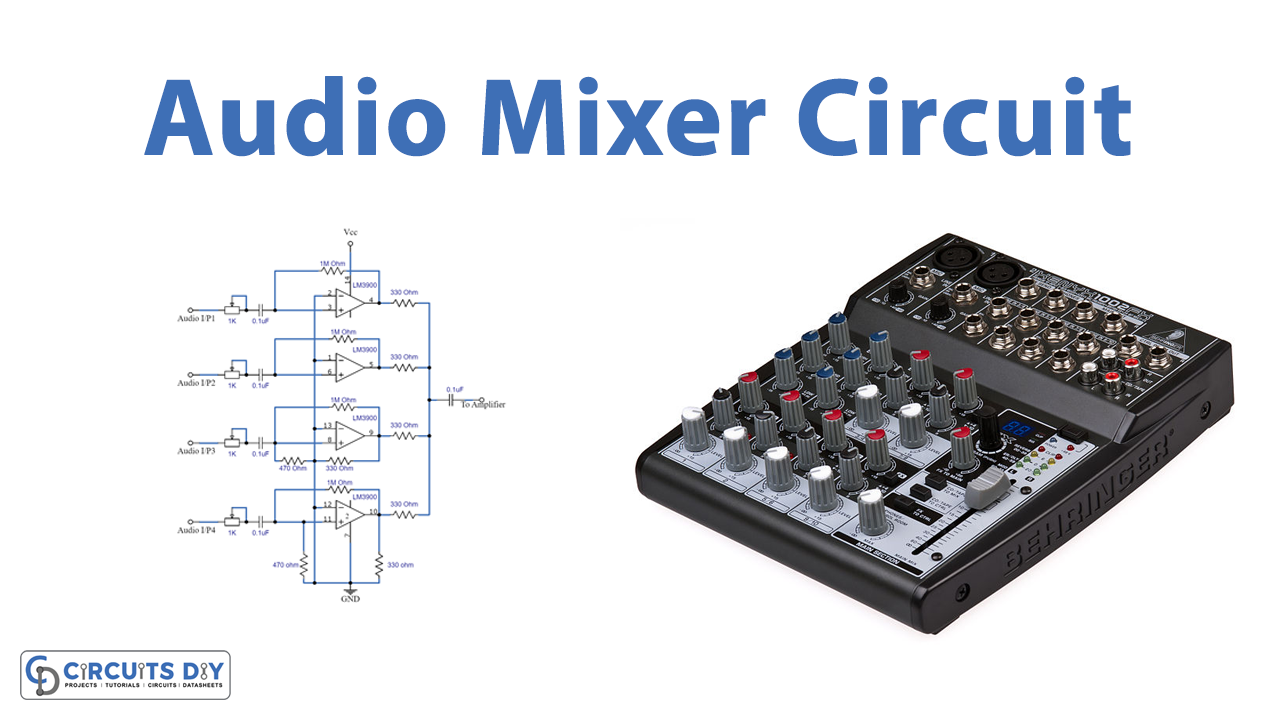
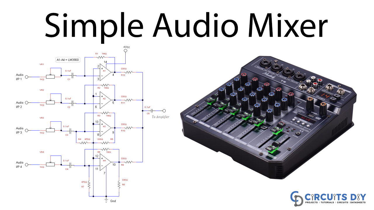
A simple multi-channel audio mixer circuit using LM3900 quad amplifier is given below. The circuit consists of 4 channel quad amplifier (LM3900). Two mic audio inputs and two direct line inputs are available in this circuit. By adding the same circuit parallel with this, you can increase the number of inputs according to the applications.
Connecting Mixer To Amplifier Diagram General Wiring Diagram
This circuit diagram serves as a blueprint for building a high-quality audio mixer with various inputs and outputs. The professional audio mixer circuit diagram includes components such as input channels, faders, equalizers, and output channels. Each input channel typically consists of a microphone or line input that can be adjusted with a gain.

audio mixer schematic Wiring Diagram and Schematics
A 6 channel audio mixer circuit typically consists of several key components, including a preamplifier, tone control circuit, and a mixing circuit. The preamplifier boosts the weak audio signals from each input source to a suitable level for further processing.. An audio mixer circuit diagram is a schematic representation of the circuitry.
4 Simple Audio Mixer Circuits diagram using FET and ICs
For this tutorial, we will build a mixer of our own design. Our mixer will have two stages: one input pre-amplifier per channel and an output summing amplifier. The schematic below is for a mono three-channel mixer with a master volume. To make this a stereo mixer, simply duplicate the circuit for the other channel.
Audio Mixer Circuit Diagram With Pcb Layout
Audio Output Wiring. The main output signal is wired to the main output jack with a 1K ohm resistor on each channel. Potentiometer front output to 1K ohm resistor to audio jack right channel (pin 2) Potentiometer back output to 1K ohm resistor to audio jack left channel (pin 3) This guide was first published on Jan 12, 2022.
How to Build an Audio Mixer Circuit Basics
The mixer circuit consists of 6 channels with monophonic channels from 1-4 while stereo channels for 5-6. The number of input channels can be varied while choosing between mono and stereo channels. The potentiometer RV1-6 regulates the sound level and drives each channel. The balancing between two channels is achieved by RV7-12.
Audio Mixer Schematic Wiring Diagram
Mixer Like This ( Watch Here ) 1) Components That I want to use : 3.5 mm mono female jack for input. I want to use as input : (1) Dynamic mic. (2) Condenser Microphone. (3) 3.5mm Stereo Mic. for Stereo to Mono conversion, I will use an adapter. I want to use 5v DC mobile charger as a power supply.
Sound Mixer Audio Mixer Circuit Diagram / Complete Circuit Diagram Of The Public Address Audio
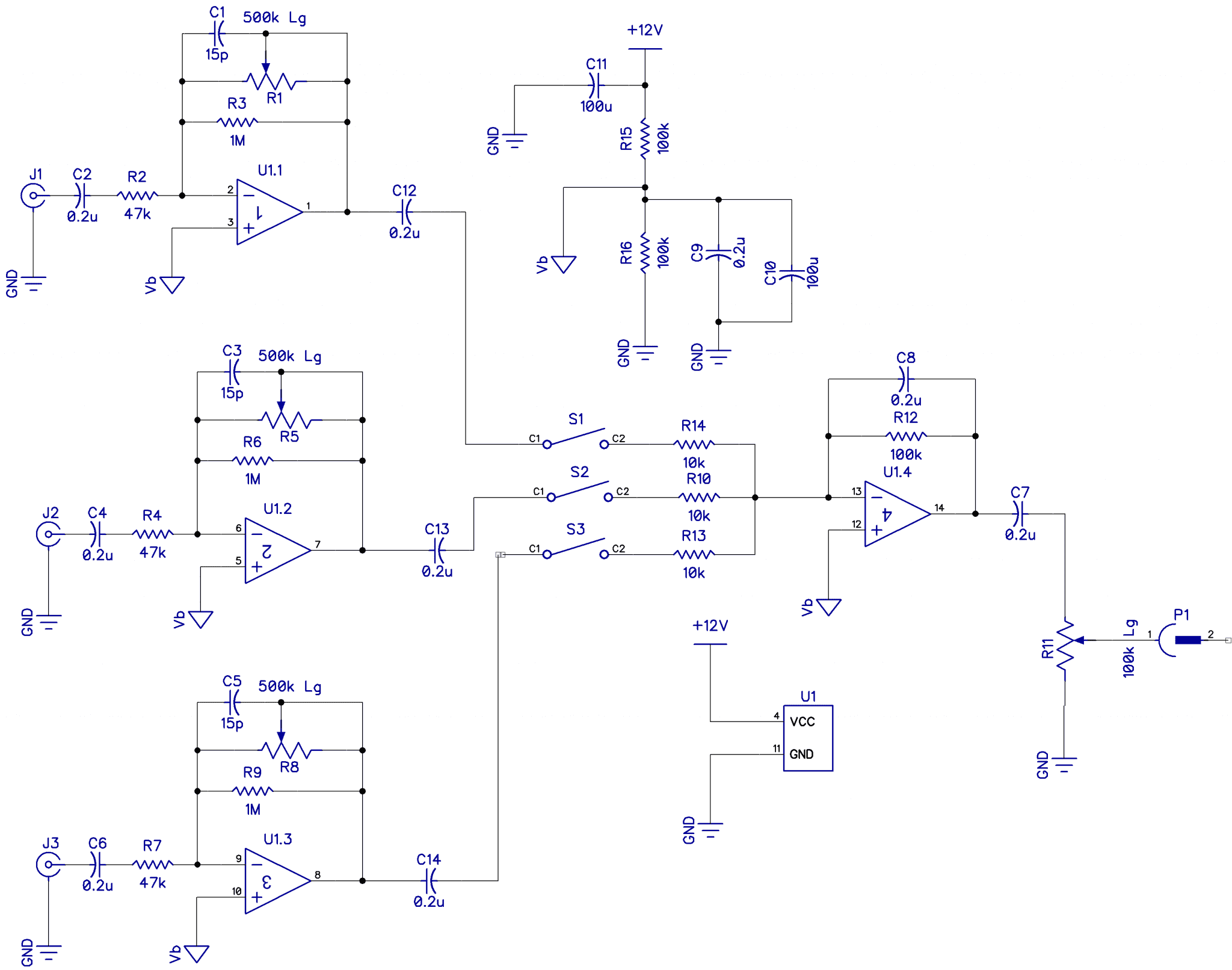
An audio Circuit mixer/ mixing console is a device that combines, then modifies audio signals. Afterward, there's a summation of the modified audio signals to create output signals.. 4-channel audio mixer circuit using Op-Amp. How it Works . Consider the simple circuit diagram below for an elaborate explanation; Here, the operational.

25 Audio Mixer Setup Diagram Wiring Database 2020
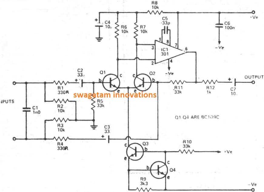
Video Amplifier. From Figure 2.15, you can see the circuit of typical video amplifier utilising a sole 2N3819 FET. The circuit delivers a voltage gain of 5: the maximum signal input before output-peak clipping, at 1 MΩ load, is 0.6 V rms for 3 V rms output. For increasing gain, you may cascade the stages.

Audio Mixer with Multiple Controls Full Circuit Diagram Available Circuit diagram, Audio
Audio Mixer by IC LF353. 3 CH MIC preamplifier with Mixer using LM348. If you are looking for a mixer with a microphone, and can easily make your own.I highly recommend this circuit.It is a microphone pre-amplifier for 3-channel or 3-channel mixer itself. When looking at the circuit, we have featured the use of a single integrated circuit LM348.
Sound Mixer Audio Mixer Circuit Diagram / SIMPLE_UTILITY_MIXER Mixer Audio_Circuit Circuit
Step 1: Circuit Diagram. This circuit is actually really simple. All the complexity is due to repetition. Basically, all circuits are as follows: input --> output. For an audio mixer, you need a resistor on each input. So, we have: input --> resistor --> output. But, it's stereo so you have to do everything twice.